Borehole equipment position detection system

a technology for positioning detection and equipment, which is applied in the direction of borehole/well accessories, surveys, instruments, etc., can solve the problems of major leakage to the environment, explosion or explosion, and subsea wells also create additional complications, etc., to achieve no disconnect and make-up interface, easy maintenance, and no damage to the surface.

Inactive Publication Date: 2007-09-25
COOPER CAMERON CORP
View PDF34 Cites 79 Cited by
  • Summary
  • Abstract
  • Description
  • Claims
  • Application Information

AI Technical Summary

Benefits of technology

[0040]The data input means is preferably a further sensor of the type used in the bore and it can therefore measure accurately the diameters and the lengths of all equipment run or pulled through the drilling vessel's drill floor. This information can be enhanced by referencing detailed product specifications which could include internal diameters, type of connection, strength and identification number. This would then provide a cross reference between what is actually run and what was scheduled to be run.
[0048]The down hole sensor(s) is (are) preferably located in a retrievable part of the LRP / riser system, such as the low pressure area of the BOP / riser, thereby allowing easier maintenance, service and repair. Additionally no disconnect and make-up interface is required compared with a BOP stack mounted sensor system.

Problems solved by technology

A subsea well also creates additional complications in respect to a well kick operation or underbalance drilling (i.e. snubbing in or out of the hole) and the requirement to carry out an emergency disconnect and later the reestablishment of the well.
A blow out can result in major leak to the environment which can ignite or explode, jeopardizing personnel and equipment in the vicinity, and pollution.
Failure to do so caused by weather conditions, current forces, equipment malfunctions, drift off or drive off, fire or explosion, collision of other marine incidents means it is necessary if possible to make the well safe, isolate the well at the seabed and disconnect the riser system.
Therefore, on a number of occasions, the accuracy of the tally is questionable.
It is easy for minor errors in measurement of each component to add up to a significant error over the length of the string.
A further problem is that even when the measurements are accurately taken at the rig, these measurements are passive, i.e. on unstressed dimensions of the component.
Furthermore, as the riser extending between the wellhead and the drill rig may be 2000-3000 m in length, it is subject to subsea currents and may be caused to “snake” between the rig and the wellhead.
Additional problems are encountered as the drilling rig heaves on the sea surface such that its position, which is dependent on the tide and the vessel draft, is constantly changing with respect to the sea bed.
As the rig can heave in a matter of seconds, it can, in rough conditions, be impossible to determine accurately the position of the string given that the calculations required at present are cumbersome and complex.
It is therefore difficult to determine accurately what component is at any given depth in a quick and accurate manner.
The shear blind rams are activated with only a set force and therefore, should the rams close on a section of equipment which is significantly larger than the shear capability of the rams, for example on a joint between adjacent pipe sections, the rams may not fully sever the drill string thereby not closing sufficiently to seal the well and allow an emergency disconnect to be carried out correctly.

Method used


Image

  • Borehole equipment position detection system
  • Borehole equipment position detection system
  • Borehole equipment position detection system

Examples


Embodiment Construction

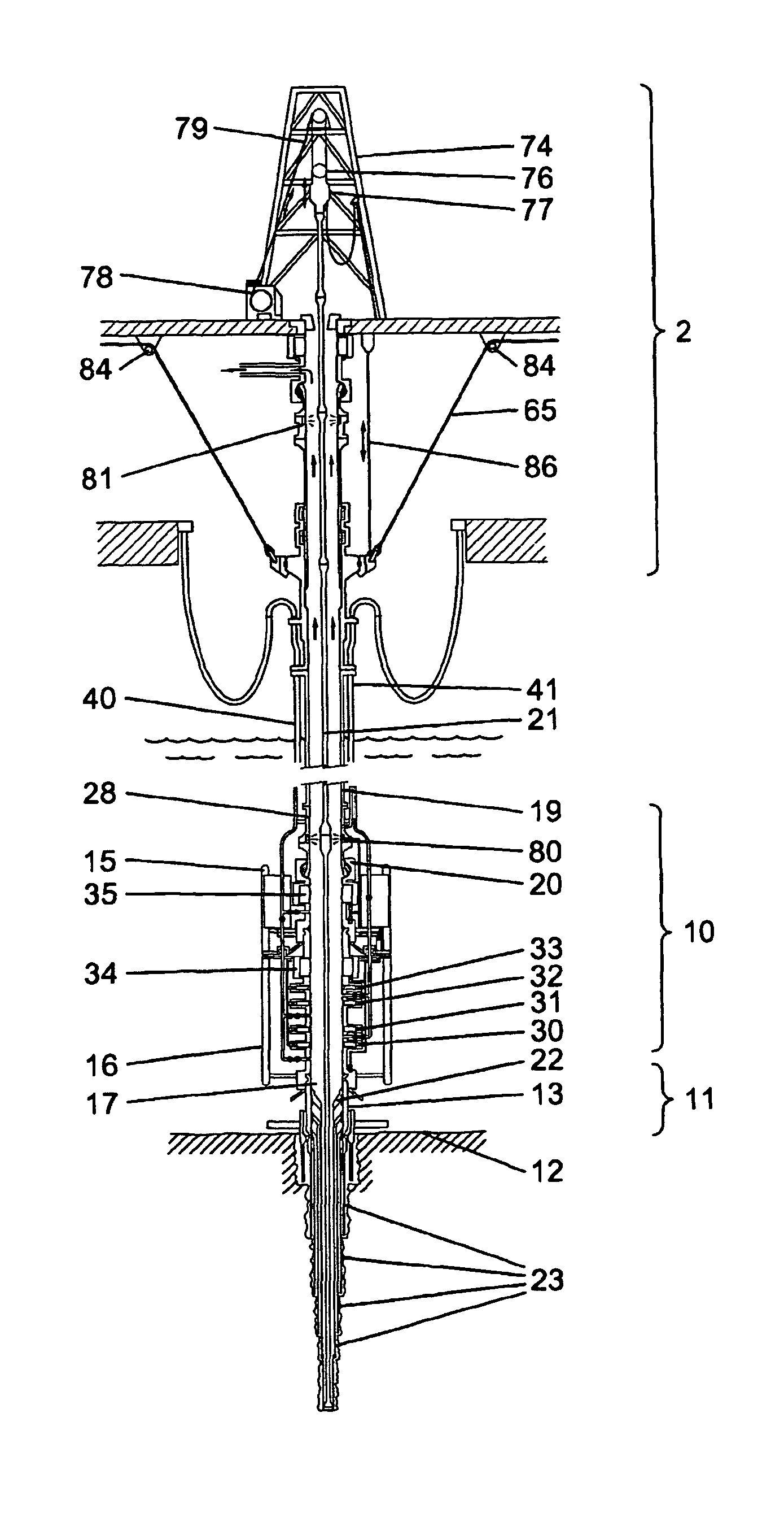
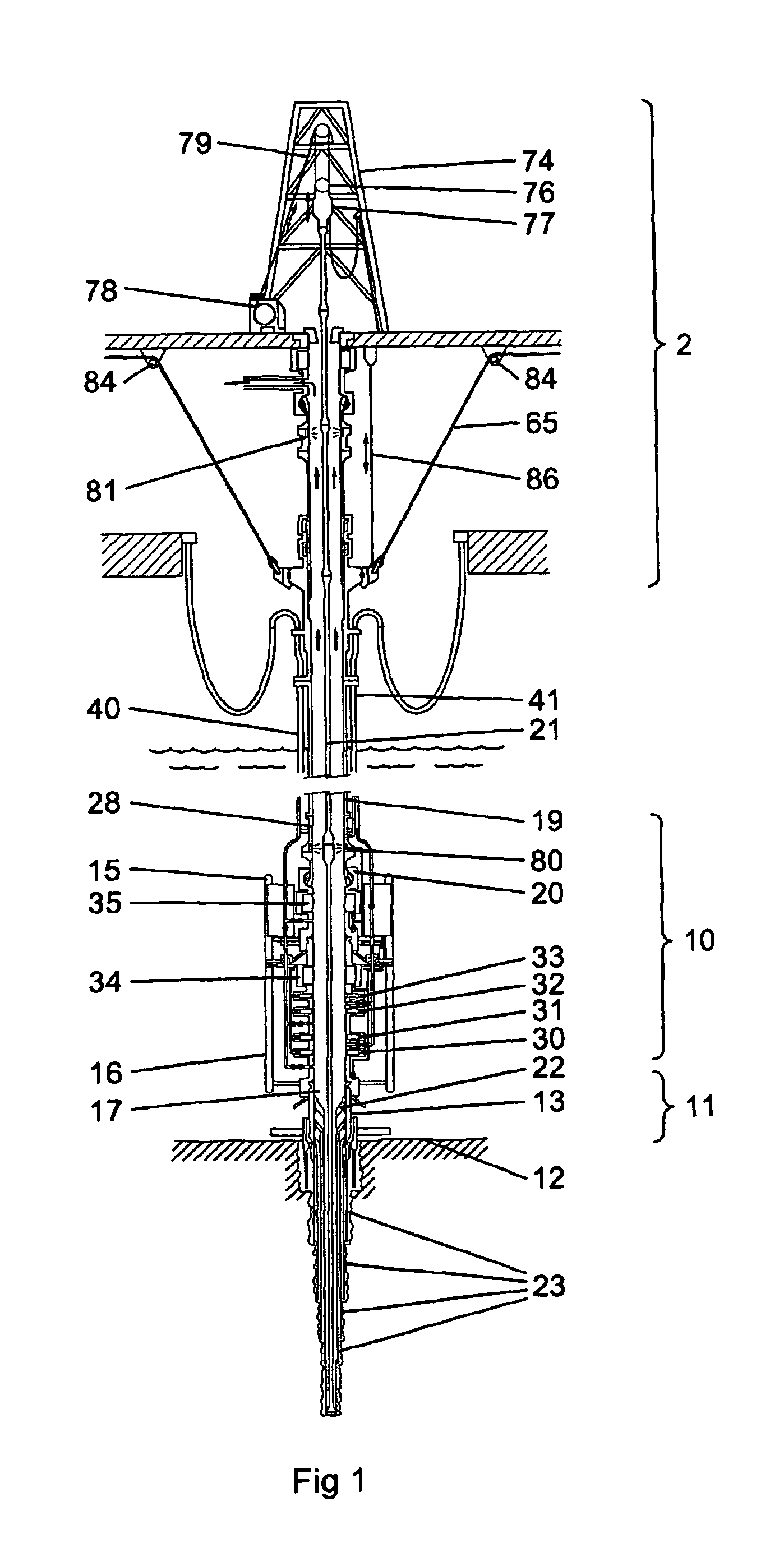
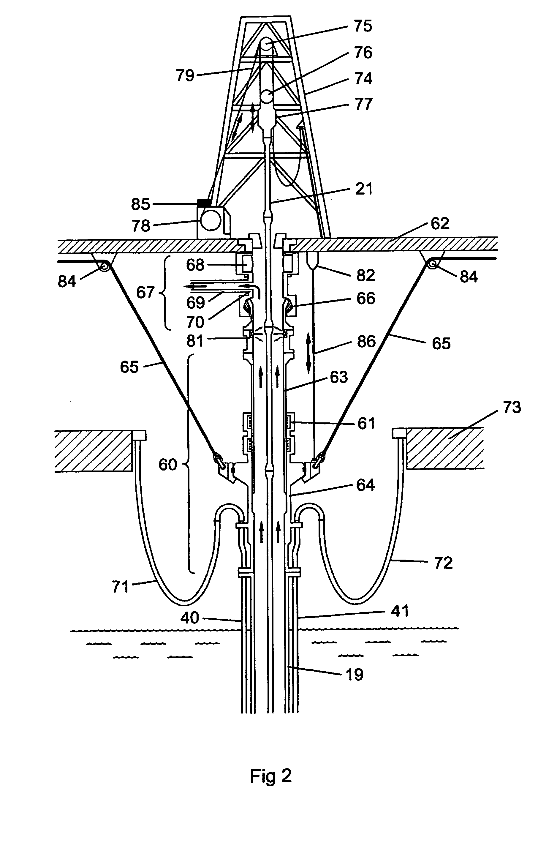
[0060]A drilling rig 2, a subsea BOP assembly 10 and wellhead assembly 11 is shown schematically in FIGS. 1 to 3. A wellhead assembly 11 is formed at the upper end of a bore into the seabed 12 and is provided with a wellhead housing 13. The BOP assembly 10 is, in this example, comprised of a BOP lower riser package (LRP) 15 and a BOP stack 16. The LRP 15 and the BOP stack 16 are connected in such a way that there is a continuous bore 17 from the lower end of the BOP stack through to the upper end of the LRP. The lower end of the BOP stack 16 is connected to the upper end of the wellhead housing 13 and is sealed in place. The upper part of the LRP 15 consists of a flex joint 20 which is connected to a riser adaptor 28, which is, in turn, connected to a riser pipe 19. The riser pipe 19 connects the BOP assembly 10 to a surface rig 2.

[0061]Within the bore 17 and the riser pipe 19, a tubular string 21 is provided. Such a string is comprised of a number of different types of component in...


PUM


Abstract

It is important to know the precise position of equipment when testing of the BOP, testing the wellhead, flow testing the well, kick control, well circulation and testing of spool trees between the wellhead and the BOP. Accordingly, there is provided a system for determining the real time position of equipment within a bore, the system including a data input means for inputting data concerning the physical characteristics of components which are run into the bore; a sensing means located, in use, within the bore and including a sensor for determining data concerning at least one physical characteristic of the equipment at a given time; a data storage means for recording the inputted data and the determined data; and a comparison means for comparing the input data and the determined data to establish which part of the equipment is being sensed by the sensor.

Description

FIELD OF THE INVENTION[0001]This invention relates to a system for determining the position of moving equipment within a bore such that, for example, an operator of a drilling system can determine the diameter, shape or orientation of the vertically moving equipment at specific locations within a well, especially at the wellhead and at the blow out preventer (BOP).BACKGROUND TO THE INVENTION[0002]When drilling in subsea applications, which can be at a water depth of as much as 10,000 feet (3,000 metres), it is important to know the location of the equipment with respect to the BOP, the wellhead, in the cased hole and in the bore of the drilled well. For example, it is important to know how equipment needs to be positioned in and along the bore for operations to be performed correctly.[0003]The prime operations are: drilling the well, casing and cementing, well testing, completion and running any equipment inside the completion, a well workover and well intervention. In addition to t...

Claims


Application Information

Patent Timeline
Patent Type & Authority Patents(United States)
IPC IPC(8): G01V1/40E21B47/09G01V3/00E21B41/00E21B47/00
CPCE21B41/00E21B47/00E21B47/09
Inventor HOPPER, HANS PAUL
Owner COOPER CAMERON CORP
Why Eureka
Try Eureka