Wheel support arrangement for an autonomous cleaning apparatus

a technology of autonomous cleaning and support arrangement, which is applied in the direction of cleaning equipment, chemistry apparatus and processes, way cleaning, etc., can solve the problems of not being able to guide such fixed-wheel cleaners past such obstacles, operation failures, vacuum cleaners, etc., and achieve the effect of facilitating the movement of the carrier and easy climbing over or otherwise avoiding objects

Inactive Publication Date: 2007-10-02
AB ELECTROLUX
View PDF29 Cites 149 Cited by
  • Summary
  • Abstract
  • Description
  • Claims
  • Application Information

AI Technical Summary

Benefits of technology

[0005]The purpose of the present invention is to provide a simple and efficient, self-adjusting motive means, such as a driving wheel assembly, for a carrier such as a surface-conditioning apparatus. In a specific application, the invention is used with the driving wheels of a cleaning apparatus, preferably a robot vacuum cleaner, whereby the vacuum cleaner easily climbs over or otherwise avoids objects and obstacles it may encounter during its operation. Another purpose of the invention is to provide at the bottom of the carrier rotatable support means, such as wheels or rollers, which are rotatably fixed to the carrier so as to define the minimum spacing, or gap, between the bottom of the carrier and the location on, or within, the surface at which the support means rest, the rotatable support means also functioning to establish a pivot, or tilting site, when the carrier is forced upwardly under the influence of an object or obstacle on the surface engaging the carrier. A further purpose of the invention is to facilitate the movement of the carrier over obstacles or obstructions by constructing the front or leading section of the bottom of the carrier so that it is slanted or inclined, with the inclination extending upwardly and outwardly from the bottom of the carrier. Yet another purpose of the invention is to provide the carrier with a control mechanism, such as a microswitch, to be engaged and operated by an actuating means associated with the motive means when the motive means, during the course of its self-adjustment, assumes a predetermined position, such as when it comes out of contact with the surface over which the carrier is traversing.

Problems solved by technology

Although the prior art arrangement described above works well under most circumstances, the fixed-wheel design with which the prior art vacuum cleaners are provided can result in operational failures when the vacuum cleaner encounters obstacles such as, for example, rugs having high or loose edges or thresholds.
It is not always possible for such fixed-wheel cleaners to be guided past such obstacles.
However, no specific wheel assembly is described for accomplishing that result.

Method used


Image

  • Wheel support arrangement for an autonomous cleaning apparatus
  • Wheel support arrangement for an autonomous cleaning apparatus
  • Wheel support arrangement for an autonomous cleaning apparatus

Examples


Embodiment Construction

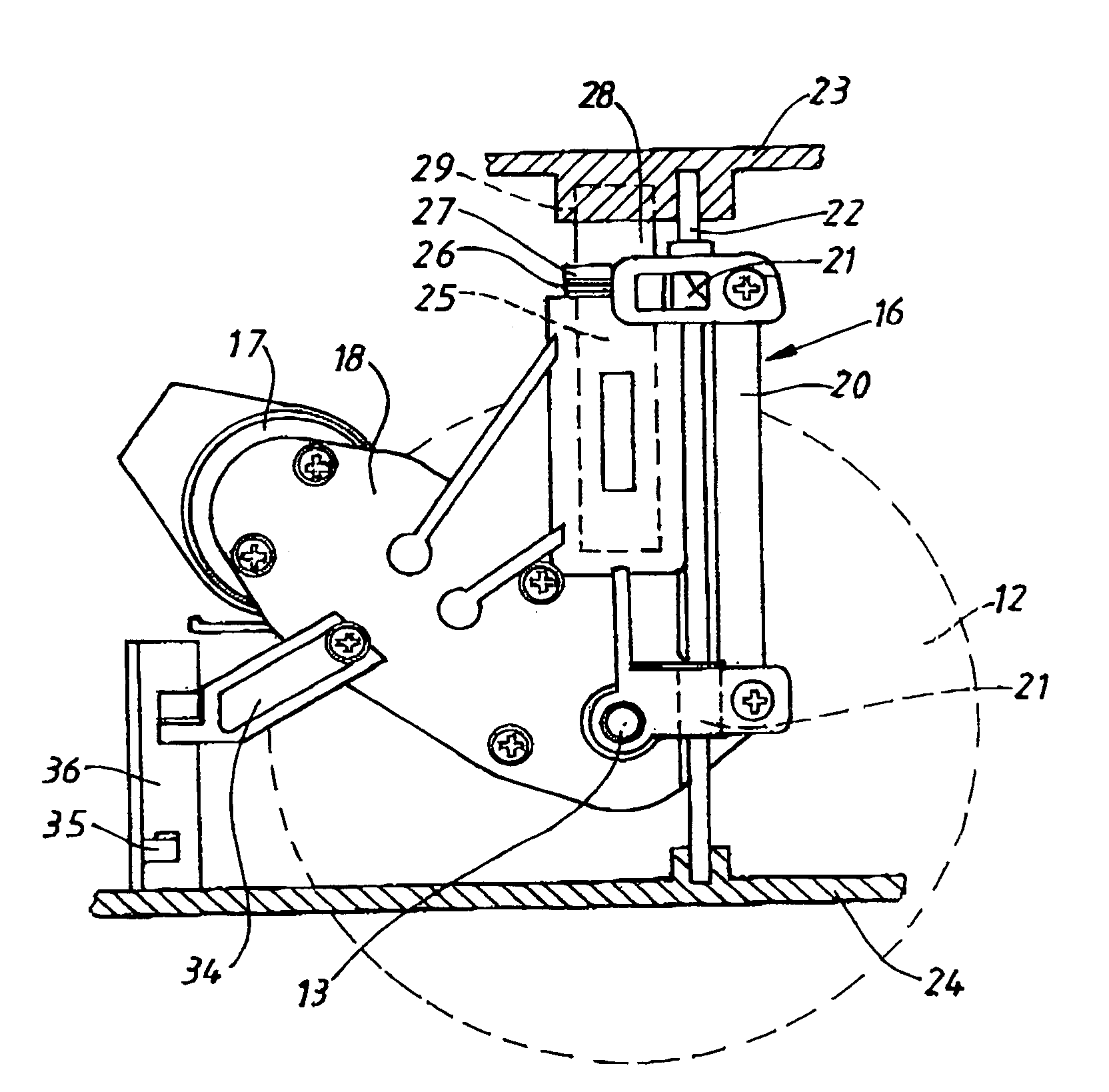
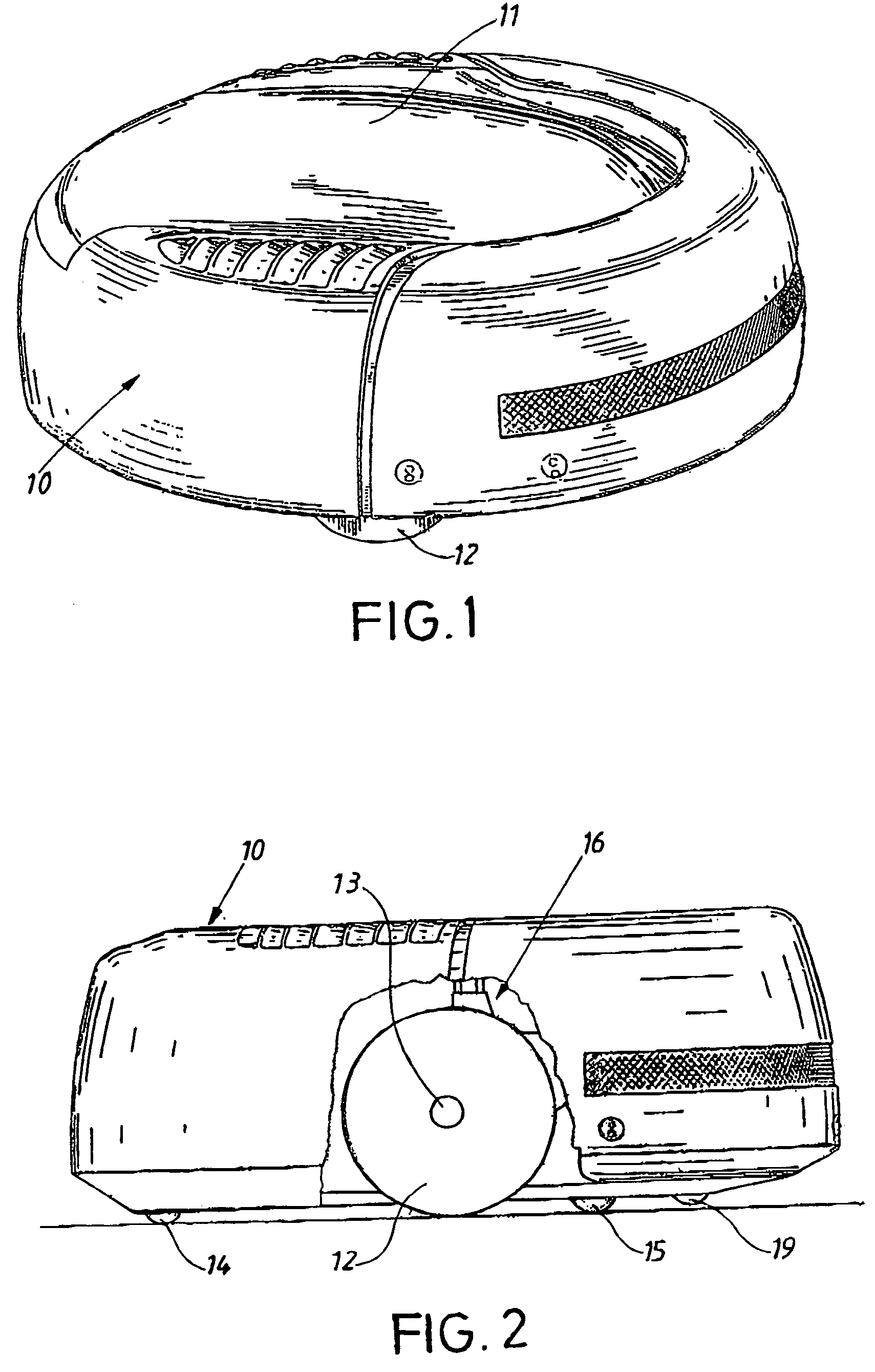
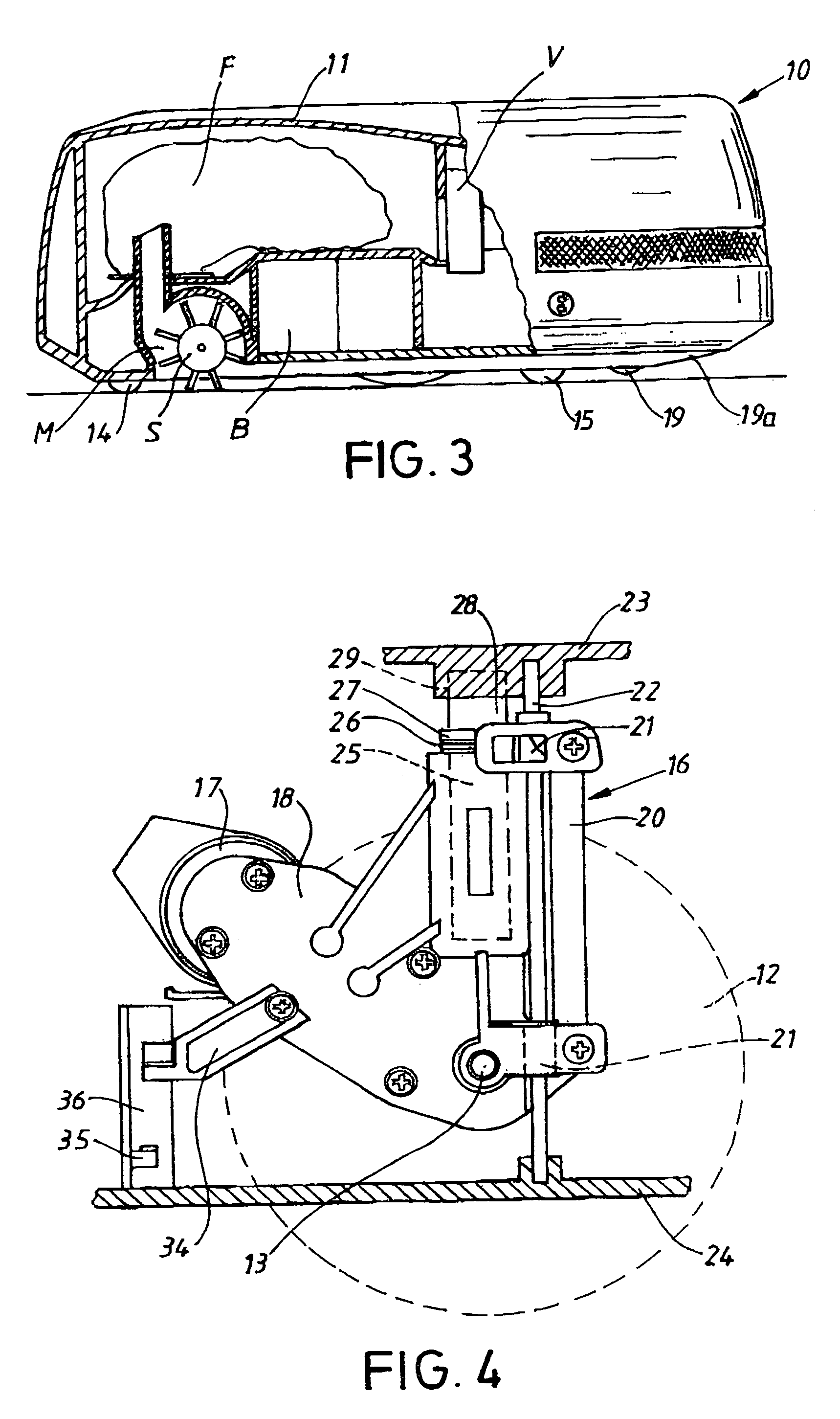
[0018]With reference to FIGS. 1-3, a carrier in the form of an autonomous cleaning apparatus, or robot vacuum cleaner, has a circular housing 10 with a cover 11 concealing a chamber in which a dust container or collector, designed as a filter cassette or a filter container F, is located. Alternatively, the housing might enclose a centrifuge cyclone separator, well known in the art, by means of which dust and particulate matter are separated from the air and are collected in the dust container F. The housing 10 also encloses a vacuum source V, typically a fan unit, that is driven by an electric source such as a battery B located in a battery holder. The container F is in fluid communication with a nozzle M located at the bottom of the housing and through which the dust and dirt-laden air is sucked and evacuated into container F. The nozzle M encloses and rotatably supports a rotating brush roll S that loosens dust and dirt from the surface over which the cleaner passes so that the su...


PUM


Abstract

A carrier, such as an autonomous cleaning apparatus, has a self-adjusting wheel assembly that can move vertically, thereby enabling the carrier to readily pass over a surface. The wheel assembly may include microswitch, which activates a control mechanism for the carrier when a wheel assembly is in a predetermined position along its path of vertical movement. Rollers can be located at the bottom of the carrier to function in cooperation with the wheel assemblies so as to facilitate the ability of the carrier to pass over obstacles. This ability may be enhanced by constructing the bottom of the front portion of the carrier so that it is slanted or inclined upwardly in a direction outward from the bottom of the carrier. A driving wheel may be rotatably attached to a wheel support, and which may also support a power source and a transmission.

Description

FIELD OF THE INVENTION[0001]The invention set forth herein relates, in general, to carriers having self-adjusting motive means that serve to transport the carriers over a surface, the self-adjusting feature allowing the motive means to move or be displaced upwardly or downwardly, thereby enabling the carrier to readily pass over the surface irrespective of the type of surface, the condition of the surface or the presence of obstructions or obstacles on the surface. The motive means can be incorporated into an assembly that includes actuating means mounted on the motive means so as to be displaced concomitantly with the motive means, as the motive means is displaced upwardly or downwardly, the actuating means thereby activating a control mechanism that controls an operational function of the carrier. The carrier can also be provided along its bottom with rotatable support means that define the minimum spacing, or gap, between the bottom of the carrier and the location on, or within, ...

Claims


Application Information

Patent Timeline
Patent Type & Authority Patents(United States)
IPC IPC(8): A47L9/00
CPCA47L9/009A47L2201/04
Inventor HAEGERMARCK, ANDERSDANESTAD, ULRIKMENNBORG, LARS
Owner AB ELECTROLUX
Why Eureka
Try Eureka