
Semiconductor device, circuit substrate, electro-optic device and electronic appliance

a technology of electrooptic devices and semiconductors, applied in the direction of semiconductor/solid-state device details, radiation controlled devices, instruments, etc., can solve the problems of difficult to absorb the warpage of ic chips as well as glass substrates, difficult to cope with the narrowing of bump electrode pitch, and scratched the top part of them, etc., to achieve high-reliability conductive connections

Inactive Publication Date: 2007-10-02
SEIKO EPSON CORP
View PDF12 Cites 8 Cited by
  • Summary
  • Abstract
  • Description
  • Claims
  • Application Information

AI Technical Summary

Benefits of technology

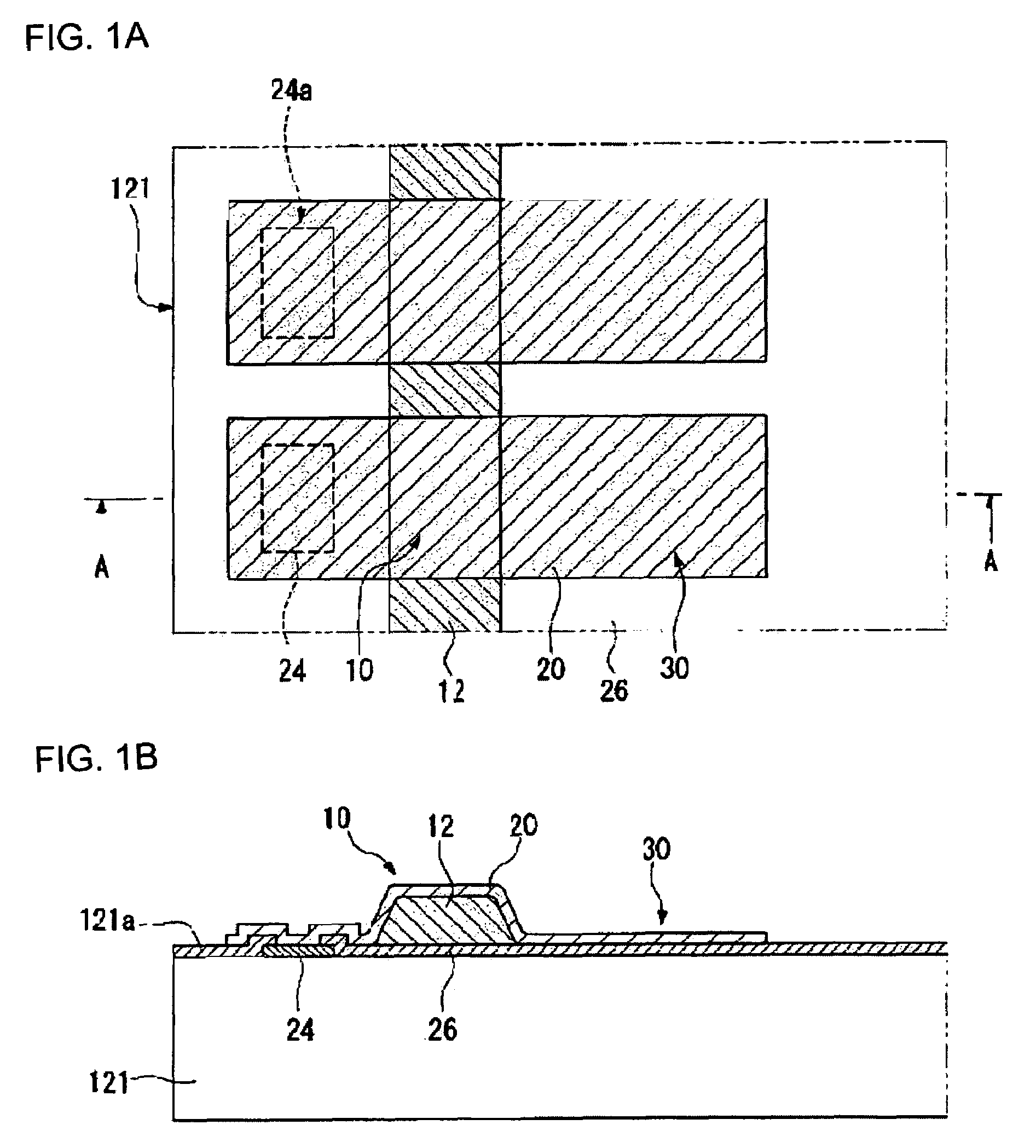
[0016]With this structure, the resin bump electrode, which serves as the conductive connection part to the opposing substrate, is formed with the resin projection and the conductive film on the surface thereon. The testing electrode is formed in the opposite side of the electrode pad across that resin bump electrode, thus by having the test probe contact the testing electrode, the conductive connectivity check between the resin bump electrode and the electrode pad can be performed easily. Moreover, even when part of the conductive film that composes the testing electrode is scratched off by the contact with the test probe, there is no effect to the conductive function of the semiconductor device. Thus, it is possible to secure a conductive connection with the opposing substrate.
[0033]With this structure, it is possible to provide the electronic appliance with a highly reliable conductive connection.

Problems solved by technology

When mounting the IC chip using a hard silicon substrate on a hard glass substrate, it is difficult to absorb the warpage of the IC chip as well as the glass substrate.
Hence, with known bump electrodes, it has been difficult to cope with the narrowing of the bump electrode pitch.
However, contacting the top part of the bump electrode with the test probe involves the problem of the top part thereof being scratched off.
Yet, in this case, it is not possible to test the entire conductive connectivity status from the electrode pad 24 to the resin bump electrode 10.
Hence, if the test probe contacts the conductive film 20 at the testing part, the insulation film 26 composed of brittle material may be damaged by the shock of the contact.
Moreover, even when part of the conductive film that composes the testing electrode is scratched off by the contact with the test probe, there is no effect to the conductive function of the semiconductor device.

Method used


Image

  • Semiconductor device, circuit substrate, electro-optic device and electronic appliance
  • Semiconductor device, circuit substrate, electro-optic device and electronic appliance
  • Semiconductor device, circuit substrate, electro-optic device and electronic appliance

Examples


first embodiment

THE FIRST EMBODIMENT

[0044]First, the first embodiment of the present invention is described using FIG. 1 through FIG. 3.

[0045]FIG. 1 is an explanatory drawing of the semiconductor device in the first embodiment. A semiconductor device 121 in the first embodiment includes: an electrode pad 24 and a resin projection 12 formed on an active surface 121a; a conductive film 20 deposited from a surface of the electrode pad 24 to a surface of the resin projection 12; and a resin bump 10 is formed with the resin projection 12 and with the conductive film 20. Further, a testing electrode 30 is formed with the conductive film 20 that is extended and applied to the opposite side of the electrode pad 24.

[0046]The Semiconductor Device

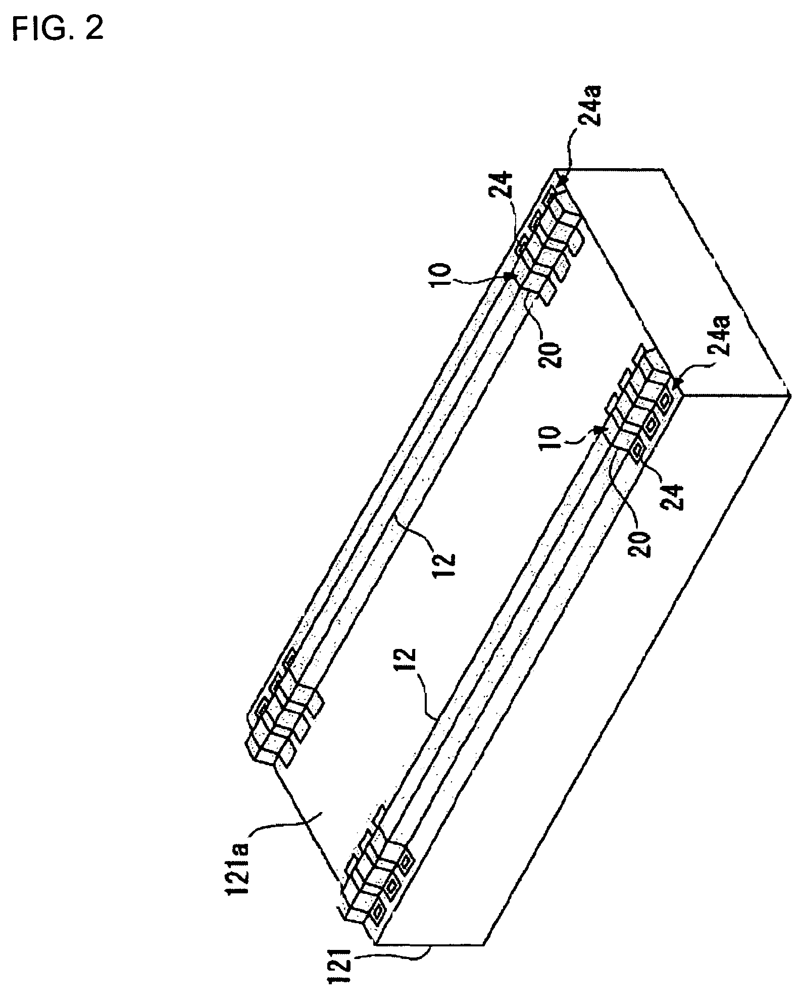
[0047]FIG. 2 is an oblique drawing of the semiconductor device in the first embodiment. The semiconductor device 121 has, for example, an IC chip that drives the picture element of the liquid crystal display device. Under its active surface, a plurality of electric e...

second embodiment

THE SECOND EMBODIMENT

[0062]Hereafter, the semiconductor device in the second embodiment of the present invention is described using FIG. 4.

[0063]FIG. 4 is an explanatory drawing of the semiconductor device in the second embodiment. FIG. 4A is a magnified top view drawing of the periphery of the resin bump electrode 10, and FIG. 4B is a sectional side view drawing of the section B-B line in FIG. 4A. As shown in FIG. 4, in the semiconductor device 121 in the second embodiment, a resin layer 32 is formed in the inner side of the array of electrode pads 24a on the active surface 121a. On the surface of the resin layer 32, the resin projection 12 is formed. The conductive film 20 is extended and applied, from the electrode pad 24 to its opposite side across the resin projection 12, and the conductive film 20 is deposited on the surface of the resin layer 32. Hence the testing electrode 30 is formed. Here, the detailed description is omitted for the part that has same structure as that of...

third embodiment

THE THIRD EMBODIMENT

[0069]Hereafter, the semiconductor device in the third embodiment of the present invention is described using FIG. 5.

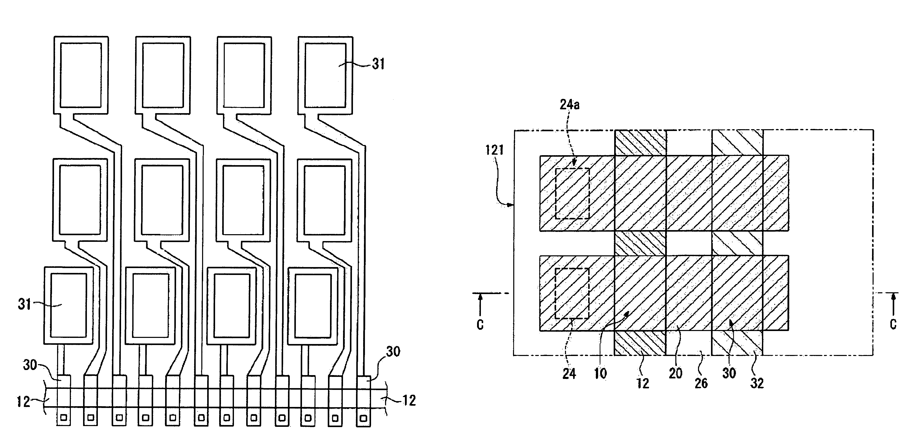
[0070]FIG. 5 is an explanatory drawing of the semiconductor device in the third embodiment. FIG. 5A is a magnified top view drawing of the periphery of the resin bump electrode 10, and FIG. 5B is a sectional side view drawing of the section C-C line in FIG. 5A. As shown in FIG. 5, in the semiconductor device 121 in the third embodiment, the resin projection 12 is formed in the inner side of the array of electrode pads 24a on the active surface 121a. The resin layer 32 is formed in the inner side of the resin projection 12 on the active surface 121a. The conductive film 20 is extended and applied, from the electrode pad 24 to its opposite side across the resin projection 12, and that conductive film 20 is deposited on the surface of the resin layer 32. Thus the testing electrode 30 is formed. Here, the detailed description is omitted for the part th...


PUM

PropertyMeasurementUnit
thicknessaaaaaaaaaa
conductiveaaaaaaaaaa
photosensitiveaaaaaaaaaa

Abstract

A semiconductor device in the first embodiment includes: an electrode pad and a resin projection, formed on an active surface; a conductive film deposited from a surface of the electrode pad to a surface of the resin projection; a resin bump formed with the resin projection and with the conductive film. The semiconductor device is conductively connected to the opposing substrate through the resin bump electrode. The testing electrode is formed with the conductive film that is extended and applied to the opposite side of the electrode pad across the resin projection.

Description

RELATED APPLICATIONS[0001]This application claims priority to Japanese Patent Application No. 2004-175534 filed Jun. 14, 2004 which is hereby expressly incorporated by reference herein in its entirety.BACKGROUND[0002]1. Technical Field[0003]The present invention relates to a semiconductor device, a circuit substrate, an electro-optic device, and an electronic appliance.[0004]2. Related Art[0005]A semiconductor device such as an Integrated Circuit chip, etc. is mounted on a substrate of a circuit substrate or a liquid crystal display device that is mounted on various kinds of electronic appliances. For example, in a liquid crystal display device, an IC chip for driving liquid crystal designed to drive a liquid crystal panel is mounted on the glass substrate (opposing substrate) that composes the liquid crystal panel (so called Chip On Glass structure). When mounting the IC chip using a hard silicon substrate on a hard glass substrate, it is difficult to absorb the warpage of the IC c...

Claims


Application Information

Patent Timeline
Patent Type & Authority Patents(United States)
IPC IPC(8): H01L23/48G02F1/1345G09G3/00H01L21/3205H01L21/60H01L23/52H01L27/146H01L29/40
CPCG09G3/006H01L27/14601H01L2924/01079H01L2924/01046H01L2924/01078H01L2224/16H01L2224/05022H01L2224/05548H01L2224/05001H01L2224/05124H01L2224/05624H01L2224/05644H01L2224/05647H01L2224/05655H01L2224/05664H01L2224/05666H01L2224/05671H01L2224/05684H01L2224/13008H01L24/13H01L24/03H01L24/16H01L2924/0001H01L2224/0615H01L2224/02377H01L24/05H01L24/02H01L2924/00014H01L2224/02H01L23/48
Inventor TANAKA, SHUICHIITO, HARUKIARUGA, YASUHITOTAMURA, RYOHEITAKANO, MICHIYOSHI
Owner SEIKO EPSON CORP
Learn More