Method for removing air wave effect from offshore frequency domain controlled-source electromagnetic data

a technology of electromagnetic data and controlled-source frequency domain, applied in the field of geophysical prospecting, can solve the problems of air wave interference, noise in field data, air wave effect problem,

Active Publication Date: 2007-10-02
EXXONMOBIL UPSTREAM RES CO
View PDF8 Cites 28 Cited by
  • Summary
  • Abstract
  • Description
  • Claims
  • Application Information

AI Technical Summary

Problems solved by technology

Air wave interference is a problem when measurements are made in the frequency domain, i.e., when the source continues to transmit its signals while data are being collected at the receivers.
Matters would be even worse for field data with noise.
The results from this example clearly demonstrate the problem of the air wave effect.
They pointed out that the effect can be incorporated into the theory if both water depth and source location are accurately determined, but they did not disclose any method to compute the effect or remove it from CSEM data.
However, the tactics of working outside of the air wave dominant range by carefully choosing transmission frequency and survey prospects cannot be used for prospects where the air wave effect is unavoidable for frequencies which can excite targets to generate recordable signals.

Method used


Image

  • Method for removing air wave effect from offshore frequency domain controlled-source electromagnetic data
  • Method for removing air wave effect from offshore frequency domain controlled-source electromagnetic data
  • Method for removing air wave effect from offshore frequency domain controlled-source electromagnetic data

Examples


examples

[0043]All of the following examples assume a unit-strength transmitter generating radiation at a frequency of 0.25 Hertz. This value is chosen for illustrative purposes only and, as those skilled in the art will understand, in no way limits the present invention.

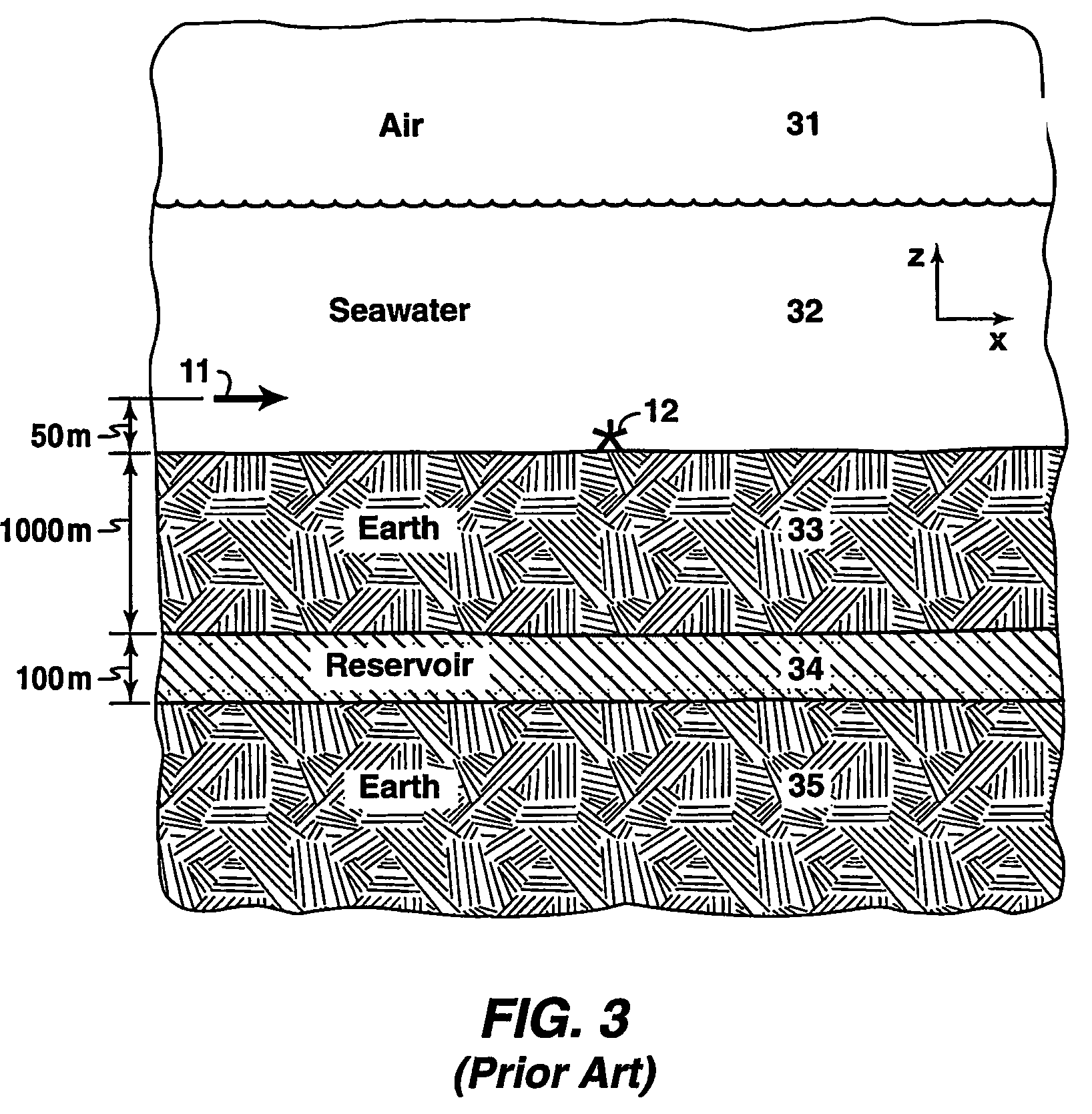
[0044]The 1-D model shown in FIG. 6A was used to generate a data set used as field data which have the air wave effect. (The reference numbers in FIGS. 5A-5B and 6A-6C are as defined for FIG. 3.) Those data (FDWA) are graphed in FIGS. 7A (amplitude vs. offset) and 7B (phase vs. offset). They are the curves of small circles, designated 71 and 72. The model is essentially the same as that of FIG. 3, except that the seawater layer is 250.0 m thick for this example. As shown in FIG. 3 (but not shown in FIG. 6), an x-directed horizontal electric dipole source is towed 50.0 m above the seafloor in the x-direction from −15.0 km to 15.0 km. A receiver located on the seafloor is directly below the mid-point of the source tow line. Th...


PUM


Abstract

A method for removing the air wave effect from offshore frequency domain controlled source electromagnetic survey data. The region of interest is modeled with (111) and without (113) a top air layer. The electromagnetic field due to the source is computed at the survey receiver positions for each source position for both models. The difference between the fields computed (116) from the two models is the air wave effect, which is then subtracted (117) from the field data for the corresponding source-receiver geometry.

Description

[0001]This application is the National Stage of International Application No. PCT / US2004 / 005024, filed Feb. 20, 2004, which claims the benefit of U.S. Provisional Patent Application No. 60 / 482,681, filed Jun. 26, 2003.FIELD OF THE INVENTION[0002]This invention relates to the field of geophysical prospecting and, more particularly, to controlled-source electromagnetic survey for hydrocarbons. Specifically, the invention is a method for removing the air wave effect encountered in such data when the data are obtained in the frequency domain.BACKGROUND OF THE INVENTION[0003]Offshore controlled-source electromagnetic (CSEM) geophysical surveys use man-made electric and magnetic sources to generate electromagnetic fields to excite the earth and deploy instruments / receivers in the ocean, on the seafloor and inside boreholes to measure electric and magnetic fields. FIG. 1 is a schematic diagram of such a survey, with electromagnetic source 11 connected by cable to a vessel and receivers 12 ...

Claims


Application Information

Patent Timeline
Patent Type & Authority Patents(United States)
IPC IPC(8): G01V3/08G06F19/00G01V3/12G01V3/38
CPCG01V3/12G01V3/083
Inventor LU, XINYOUSRNKA, LEONARD J.CARAZZONE, JAMES J.
Owner EXXONMOBIL UPSTREAM RES CO
Why Eureka
Try Eureka