
Logarithmic spectrum transmitter waveform for controlled-source electromagnetic surveying

a technology of source waveform and logarithmic spectrum, which is applied in the field of geophysical prospecting, can solve the problems of difficult to collect high signal-to-noise data for high harmonics and rapid decrease of amplitudes for higher harmonics

Active Publication Date: 2009-05-26
EXXONMOBIL UPSTREAM RES CO
View PDF13 Cites 15 Cited by
  • Summary
  • Abstract
  • Description
  • Claims
  • Application Information

AI Technical Summary

Benefits of technology

The patent describes different embodiments of periodic source waveforms for electromagnetic surveys. These waveforms have a frequency spectrum that includes four or more frequencies, with at least three of the frequencies having larger amplitudes than any other frequency. The waveforms can have a period of about one decade or more. The patent also describes different methods for generating these waveforms. The technical effect of these embodiments is that they provide more efficient and effective tools for electromagnetic surveys, allowing for better data collection and analysis.

Problems solved by technology

In current surveys, the transmitter is flown above the earth's surface by an aircraft, or towed by a vessel only once along each survey line, due to the high cost of operating the source aircraft or vessel.
With the limitation of fixed transmitter power, it is very difficult to collect high signal-to-noise data for high harmonics unless the data are summed for a very large number of cycles.
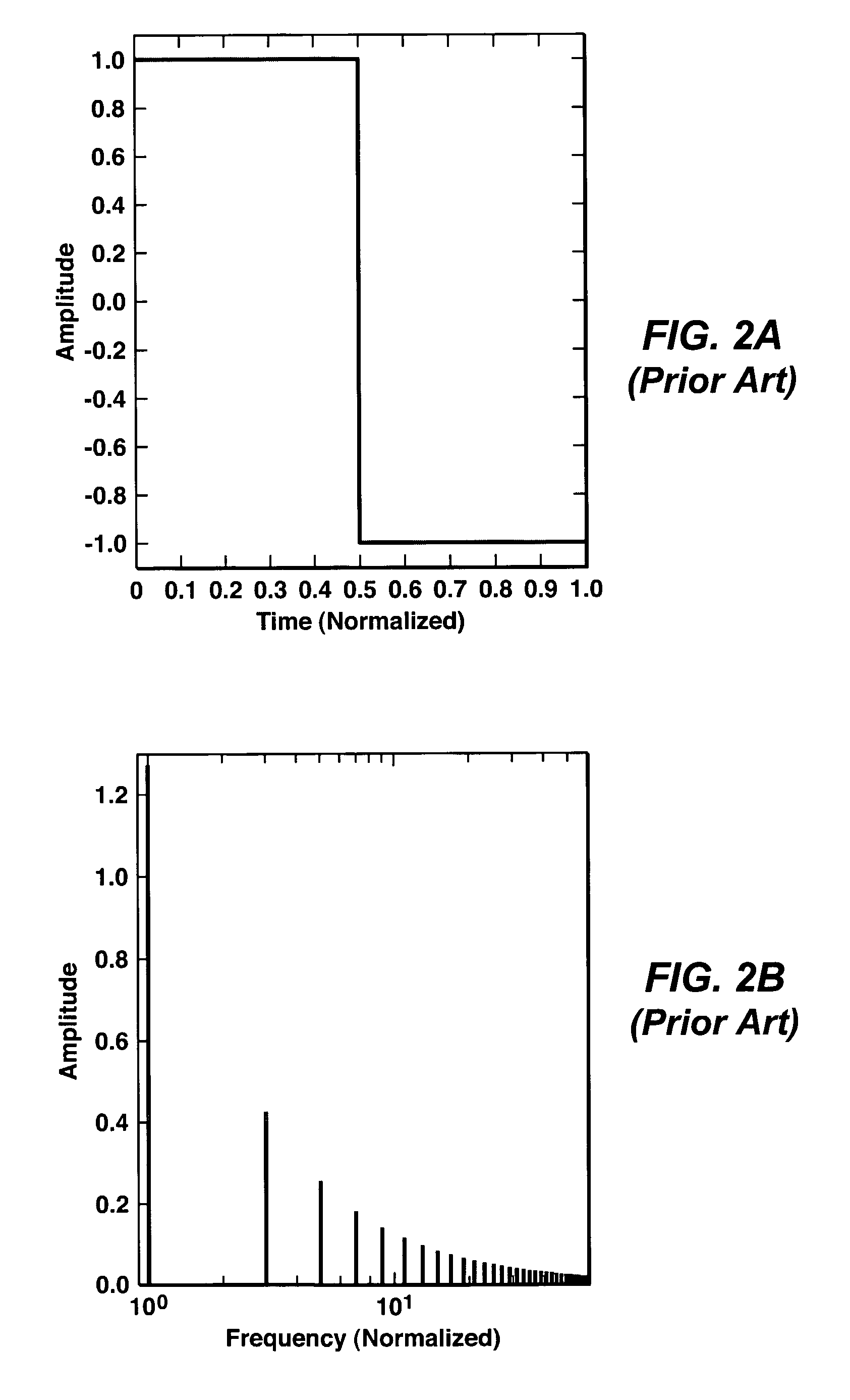
Unfortunately the frequency band covered by these two harmonics is narrow [3:1 ratio], and amplitudes for higher harmonics decrease rapidly as the frequency increases.

Method used


Image

  • Logarithmic spectrum transmitter waveform for controlled-source electromagnetic surveying
  • Logarithmic spectrum transmitter waveform for controlled-source electromagnetic surveying
  • Logarithmic spectrum transmitter waveform for controlled-source electromagnetic surveying

Examples


Embodiment Construction

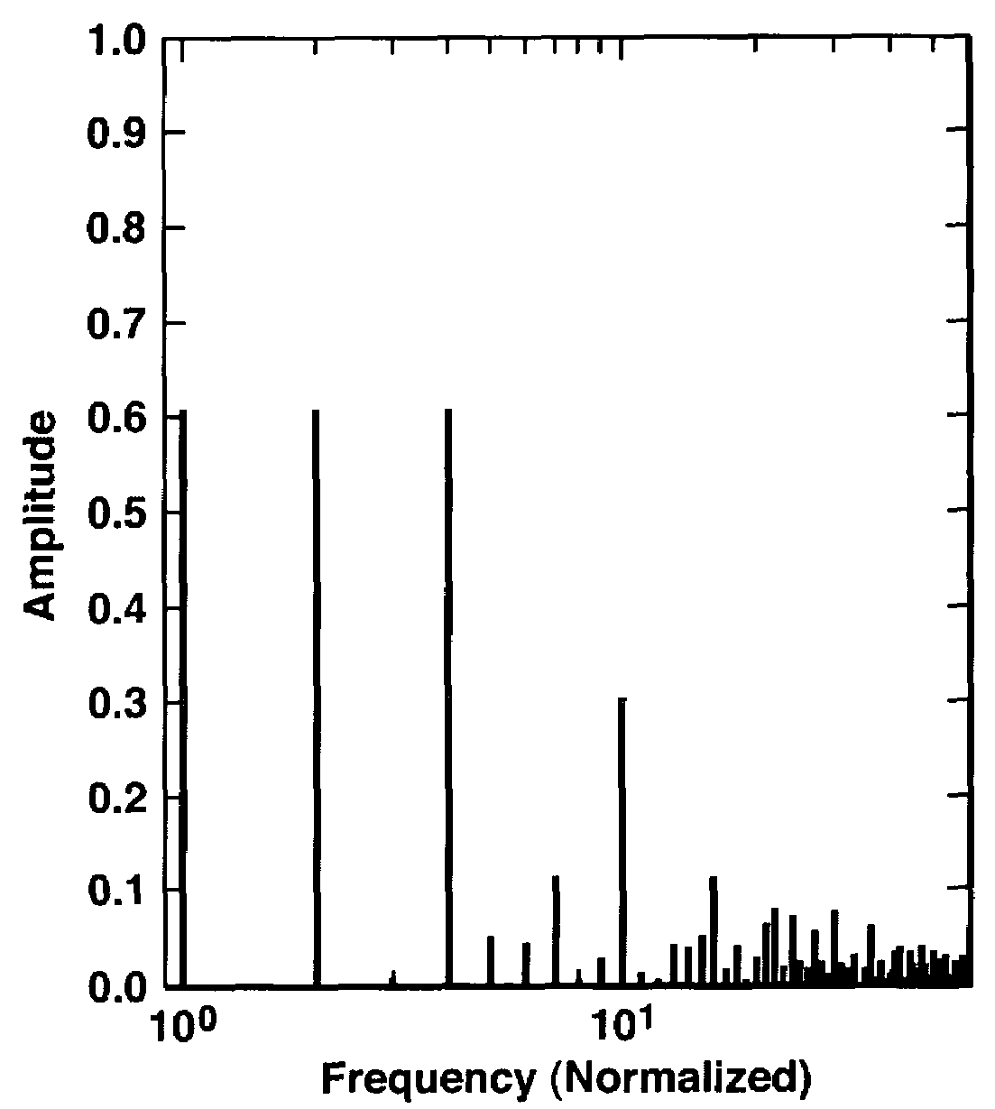
[0047]The essence of the present invention is that a source waveform for CSEM surveying should preferably have a frequency spectrum in which desired frequencies having the larger associated amplitudes are spaced substantially uniformly (i.e., at roughly equal intervals) on a logarithmic scale and cover a useful bandwidth. It is well known that, for low-frequency EM fields, effective exploration depth increases with decreasing frequency and with decreasing conductivity of the medium, according to the skin effect phenomena (J. A. Stratton, Electromagnetic Theory, MacGraw-Hill (1941); B. R. Spies, Geophysics 54, 872-888 (1989)). Since most CSEM data are collected relatively far from the source so that near-field geometric effects are negligible, an electromagnetic field at a specific frequency decays exponentially with depth for depths greater than a few source dipole lengths. The present invention enables CSEM surveying to achieve a wider probing depth with multiple frequencies in one...


PUM


Abstract

Waveforms for controlled source electromagnetic surveying. The waveforms have frequency spectra that include three or more frequencies spaced at substantially equal intervals on a logarithmic frequency scale and spanning a bandwidth of about one decade or more, at least three of which frequencies have approximately equal corresponding amplitudes.

Description

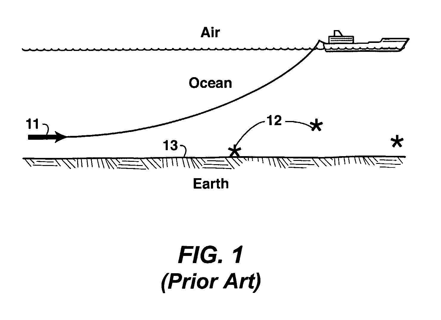
[0001]This application is the National Stage of International Application No. PCT / US2005 / 013250, filed 20 Apr. 2005, which claims the benefit of U.S. Provisional Patent Application No. 60 / 572,694, filed 20 May, 2004.FIELD OF THE INVENTION[0002]This invention relates generally to the field of geophysical prospecting and, more particularly, to controlled source electromagnetic (“CSEM”) surveys of subsurface formations. Specifically, the invention is an improved source waveform for generating CSEM fields.BACKGROUND OF THE INVENTION[0003]Controlled-source electromagnetic geophysical surveys use man-made sources to generate electromagnetic fields to excite the earth, and deploy receiver instruments on the earth's surface, on the seafloor, in the air, or inside boreholes to measure the resulting electric and magnetic fields, i.e., the earth's response to the source excitation. FIG. 1 illustrates the basic elements of an offshore CSEM survey. A vessel tows a submerged CSEM transmitter 11 o...

Claims


Application Information

Patent Timeline
Patent Type & Authority Patents(United States)
IPC IPC(8): H04L23/00G01V3/12
CPCG01V3/083G01V3/12
Inventor LU, XINYOUSRNKA, LEONARD J.
Owner EXXONMOBIL UPSTREAM RES CO
Learn More