Magnetic compass

a magnetic compass and compass technology, applied in the field of magnetic compass, can solve the problems of difficult to achieve low cost or low power consumption system, noise pick-up, significant errors of the technique, etc., and achieve the effect of easy and accurate azimuth measuremen

Inactive Publication Date: 2007-10-09
AICHI MICRO INTELLIGENT
View PDF10 Cites 15 Cited by
  • Summary
  • Abstract
  • Description
  • Claims
  • Application Information

AI Technical Summary

Benefits of technology

[0013]The present invention has been made in view of the above-mentioned problems associated with the prior art. Accordingly, it is an object of the present invention to provide a low-cost magnetic compass that enables easy and accurate azimuth measurement irrespective of its installation angle.

Problems solved by technology

However, this technique faces significant errors when the magnetic sensor is placed at an inclination.
However, the use of the inclination sensor may make it difficult to achieve low cost or low power consumption system.
Further, the inclination sensor picks up noise due to vibration or mechanical impact, which may inevitably result in the occurrence of errors.
As described above, to perform azimuth measurement using the above-mentioned azimuth measuring device, it is necessary for the user to perform the following extremely complicated operation.
For this reason, the azimuth measuring device proves extremely inconvenient and unpractical for measuring the azimuth of a movable body such as an automobile.

Method used


Image

  • Magnetic compass
  • Magnetic compass
  • Magnetic compass

Examples


Embodiment Construction

[0044]A magnetic compass according to the present invention will be described with reference to FIGS. 1 to 10.

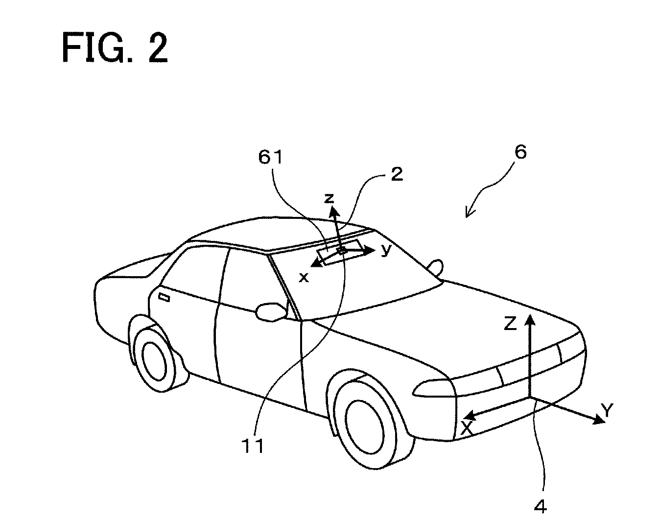
[0045]As shown in FIGS. 2 and 3, a magnetic compass 1 according to an embodiment of the present invention is mounted to a vehicle 6 and used to measure the azimuth of travel of the vehicle 6.

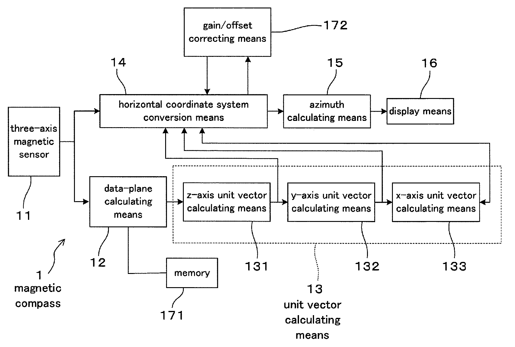
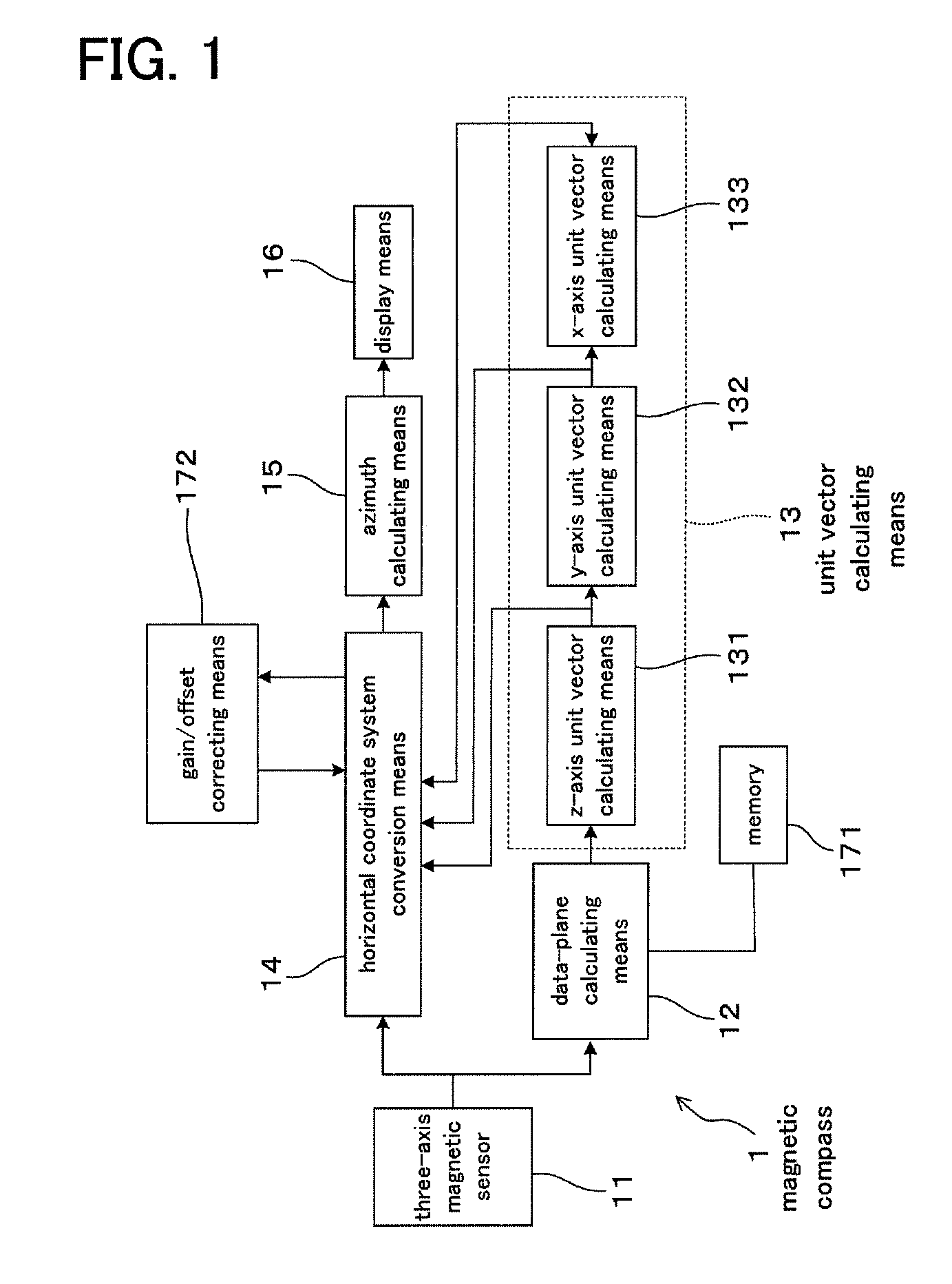
[0046]As shown in FIG. 1, the magnetic compass 1 has a three-axis magnetic sensor 11, data-plane calculating means 12, unit vector calculating means 13, horizontal coordinate conversion means 14, azimuth calculating means 15, and display means 16.

[0047]The three-axis magnetic sensor 11 detects geomagnetic vector in the form of magnetic components in the directions of three mutually orthogonal axes x, y, and z as shown in FIGS. 2 and 5.

[0048]By using geomagnetic vector detected by the three-axis magnetic sensor 11 as the three-axis magnetic sensor 11 changes its orientation to at least three different arbitrary directions within the horizontal plane, as shown in FIG. 5, the data-plane cal...


PUM


Abstract

A magnetic compass includes: a three-axis magnetic sensor for detecting geomagnetic vector as geomagnetic components in directions of three orthogonal axes x, y, and z; a data-plane calculating unit for calculating a data plane on which output data of the three-axis magnetic sensor are present in a sensor coordinate system of the three axes x, y, and z; a unit vector calculating unit for calculating unit vectors of a horizontal coordinate system of three orthogonal axes X, Y, and Z whose Z-axis runs vertically and X-Y plane defines a horizontal plane relative to the earth; a horizontal coordinate system conversion unit for converting geomagnetic components in the sensor coordinate system detected by the three-axis magnetic sensor into geomagnetic components in the horizontal coordinate system; an azimuth calculating unit for calculating azimuth based on the converted geomagnetic components in the horizontal coordinate system; and a display unit for displaying the calculated azimuth.

Description

CROSS-REFERENCES TO RELATED APPLICATIONS[0001]The present application claims priority under 35 U.S.C. §119 to Japanese Patent Application No. 2005-304226, filed Oct. 19, 2005, entitled “MAGNETIC COMPASS”. The contents of this application are incorporated herein by reference in their entirety.BACKGROUND OF THE INVENTION[0002]1. Field of the Invention[0003]The present invention relates to a magnetic compass for determining azimuth by detecting the geomagnetism.[0004]2. Description of the Related Art[0005]Conventionally, there is a technique of determining azimuth by horizontally placing a magnetic sensor with a two-dimensional direction sensitivity and detecting the horizontal component of the geomagnetism.[0006]However, this technique faces significant errors when the magnetic sensor is placed at an inclination.[0007]In view of this, in order to allow accurate azimuth to be obtained even when the sensor is placed at an arbitrary angle, there is a technique in which both a 3-axis magn...

Claims


Application Information

Patent Timeline
Patent Type & Authority Patents(United States)
IPC IPC(8): G01C17/38
CPCG01C17/38G01C17/30
Inventor HONKURA, YOSHINOBUTSUCHIDA, KATSUHIKOAOYAMA, HITOSHIKAKO, EIJI
Owner AICHI MICRO INTELLIGENT
Why Eureka
Try Eureka