Illumination devices and related systems and methods

a technology of light-emitting diodes and illumination devices, applied in the direction of optical radiation measurement, process and machine control, television system scanning details, etc., can solve the problems of limiting performance and increasing cost, led arrays designed and calibrated to produce uniform brightness and color when manufactured, and degrading with use, etc., to achieve accurate control, accurate measurement, easy and accurate measurement

Active Publication Date: 2014-07-08
LUTRON TECH CO LLC
View PDF165 Cites 16 Cited by
  • Summary
  • Abstract
  • Description
  • Claims
  • Application Information

AI Technical Summary

Benefits of technology

[0019]Although one primary application for the invention is backlights for FSC LCDs, many other applications such as solid state lighting and conventional LCDs could also benefit from the disclosed embodiments. For example, combining a photo detector, such as a photodiode or an LED or other light detecting device, with different colored LEDs, including white, in the same package enables the light produced by each such LED to be accurately measured even in the presence of significant ambient light or light from LEDs in adjacent packages. In one embodiment, a photodiode enables the temperature of the package and consequently the LEDs to be easily and accurately measured using well known techniques that inject currents into such photodiode, measure forward voltages, and calculate temperature from the results. With such measurements, the color and intensity of the light produced by such an illumination device can be accurately controlled using the methods described herein for any application. The ratio of photo currents can be used to control the relative intensity and consequently the color of light produced by the device and the absolute photo current compensated for temperature can be used to control the total intensity produced by the device.
[0020]While the embodiments described herein are applicable to a broad range of applications, it is noted, however, that the disclosed embodiments are particularly useful for FSC LCD backlights, because the colors are sequenced and as such the photo detector (e.g. photodiode, LED, etc.) can monitor the light produced by each LED in the illumination device without requiring modifications to the display timing or optics.

Problems solved by technology

LEDs are popular for such display and lamp applications due to the low cost, high energy efficiency, and long lifetime, however, variations in light output between individual LEDs and between LEDs from each color component group can limit performance and increase cost.
LED customers may either purchase only specific bins for a higher price or design products that can tolerate wider tolerances, which may limit performance.
Further, an LED array that is designed and calibrated to produce uniform brightness and color when manufactured will degrade with use.
Such color filters add cost and complexity to the design of the display and possibly more importantly for mobile devices block most of the light produced by the backlight.
The problem with RGB backlights is producing and maintaining the desired color and intensity produced by each red, green, and blue triplet.
The relatively simple approach described previously for RGB LED backlights along one or more sides of the display that uses one or more sets of photo-sensors to detect the intensity of each color component is not possible with such Sony products that support local dimming.
Since this calibration technique would disrupt any picture being observed at the time, such routine cannot be performed during normal operation of the display.
Consequently, such routine cannot be used to compensate for LED output variations due to temperature, which can change substantially during use.

Method used


Image

  • Illumination devices and related systems and methods
  • Illumination devices and related systems and methods
  • Illumination devices and related systems and methods

Examples


first embodiment

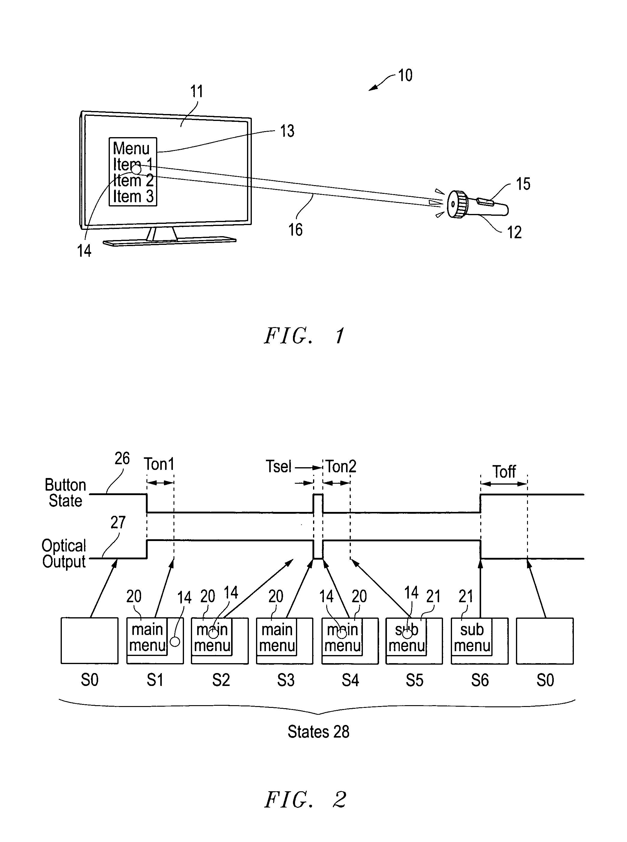
[0124]Display and optical pointer systems and related methods are disclosed that utilize LEDs in a display device to respond to optical signals from optical pointing devices. Various embodiments are described with respect to the drawings below. Other features and variations can also be implemented, if desired, and related systems and methods can be utilized, as well.

[0125]In part, the disclosed embodiments relate to displays with arrays of LEDs and associated pointing devices that communicate with individual LEDs in the arrays using visible light. The LED arrays can produce images directly as in LED billboards and sports arena scoreboards or can produce the backlight for LCD screens for instance. The pointing devices communicate with individual pixels or groups of pixels using a beam of light that may or may not be modulated with data, which is detected by the LEDs in the array that are exposed to the beam. Periodically, the LEDs in an array stop producing light and are configured w...

second embodiment

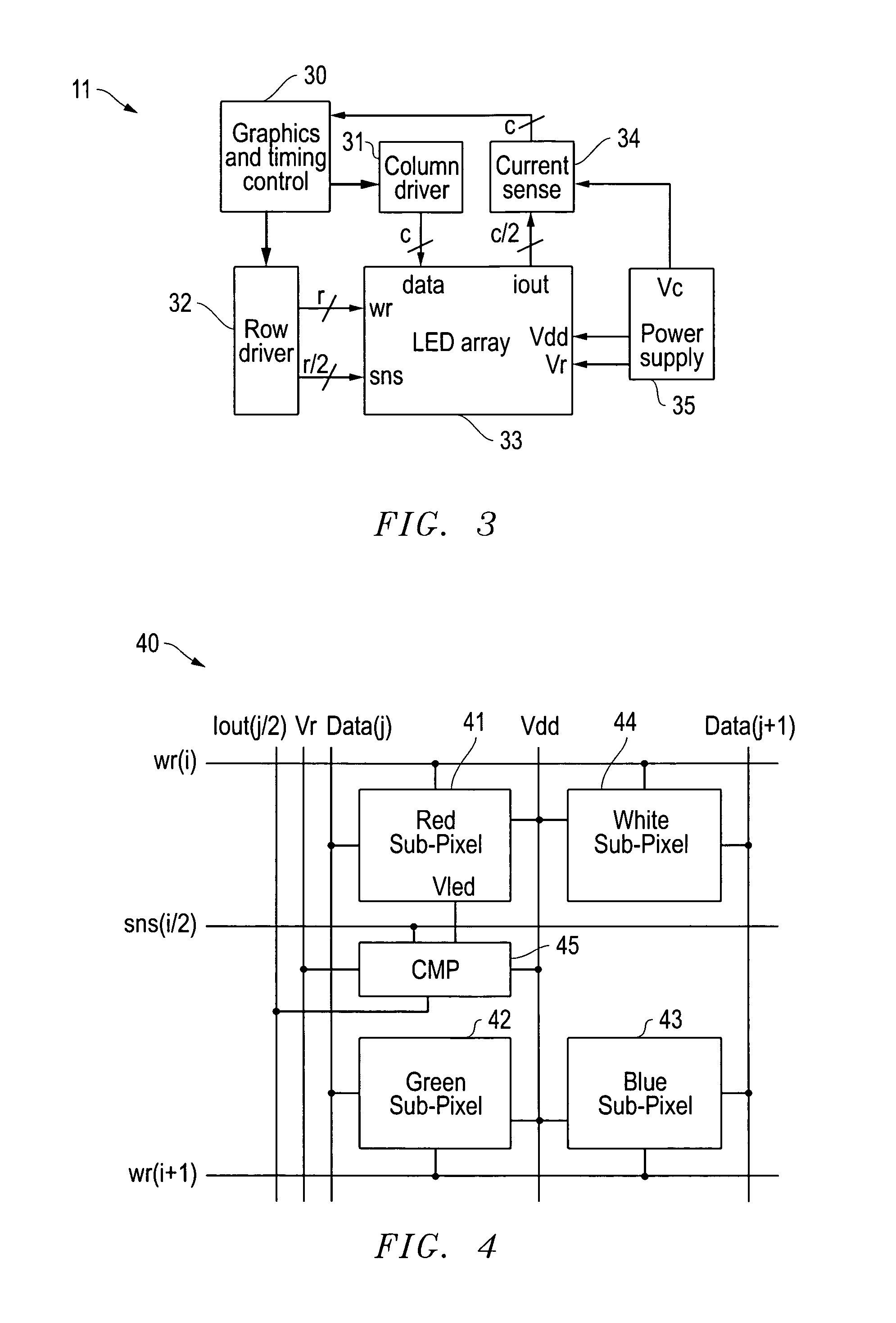
[0207]Display calibration systems and related methods are also disclosed that use the photo-sensitivity of LEDs to correct for variations between LEDs during initial production and over lifetime for display systems. Various embodiments are described with respect to the drawings below. Other features and variations can also be implemented, if desired, and related systems and methods can be utilized, as well.

[0208]In part, the disclosed embodiments relate to displays including arrays of LEDs that use the photo-sensitivity of the LEDs to correct for variations between LEDs during initial production and over lifetime of such a display. Such LED arrays can produce images directly as in LED billboards and sports arena scoreboards, and smaller Organic LED (OLED) displays, or can produce the backlight for LCD screens for instance. Variations in LED brightness and color can be compensated for in order for such a display to have uniform color and brightness. Such compensation, which is typica...

third embodiment

[0260]LED calibration systems and related methods are also disclosed that use the photo-sensitivity of LEDs to correct for variations between LEDs during initial production and over the lifetime of systems using LEDs. Various embodiments are described with respect to the drawings below. Other features and variations can also be implemented, if desired, and related systems and methods can be utilized, as well.

[0261]In part, the disclosed embodiments relate to using the photo-sensitivity of an LED to determine emission parameters such as intensity and wavelength. Applications for the disclosed embodiments include solid state lamps, LCD backlights, and LED displays for instance. Variations in LED brightness and wavelength should be compensated for in order for such devices to have uniform color and brightness. Such compensation, which is typically done by measuring the optical output of each individual LED with a camera or purchasing specially tested LEDs, is performed by simply measur...


PUM

PropertyMeasurementUnit
wavelengthaaaaaaaaaa
threshold voltageaaaaaaaaaa
voltageaaaaaaaaaa

Abstract

Illumination devices and related systems and methods are closed that can be used for LCD (Liquid Crystal Display) backlights, LED lamps, or other applications. The illumination devices can include a photo detector, such as a photodiode or an LED or other light detecting device, and one or more LEDs of different colors. A related method can be implemented using these illumination devices to maintain precise color produced by the blended emissions from such LEDs. One application for the illumination devices is backlighting for FSC (Field Sequential Color) LCDs (Liquid Crystal Displays). FSC LCDs temporally mix the colors in an image by sequentially loading the red, green, and blue pixel data of an image in the panel and flashing the different colors of an RGB backlight. Precise and uniform color temperature across such a display can be advantageously maintained by continually monitoring ratios of photodiode currents induced by the different colored LEDs in each illumination device as each color is flashed.

Description

RELATED APPLICATIONS[0001]This application claims priority to the following co-pending provisional applications: U.S. Provisional Patent Application Ser. No. 61 / 273,518 filed Aug. 5, 2009 by David J. Knapp and entitled “Display and Optical Pointer Systems and Related Methods;” U.S. Provisional Patent Application Ser. No. 61 / 273,536 filed Aug. 5, 2009 by David J. Knapp and entitled “Display Calibration Systems and Related Methods;” U.S. Provisional Patent Application Ser. No. 61 / 277,871 filed Sep. 30, 2009 by David J. Knapp and entitled “LED Calibration Systems and Related Methods;” U.S. Provisional Patent Application Ser. No. 61 / 281,046 filed Nov. 12, 2009 by David J. Knapp and entitled “LED Calibration Systems and Related Methods;” U.S. Provisional Patent Application Ser. No. 61 / 336,242 filed Jan. 19, 2010 by David J. Knapp and entitled “Illumination Devices and Related Systems and Methods;” and U.S. Provisional Patent Application Ser. No. 61 / 339,273 filed Mar. 2, 2010 by David J. ...

Claims


Application Information

Patent Timeline
Patent Type & Authority Patents(United States)
IPC IPC(8): G09G3/30G09G3/36G03B21/14G02F1/1335G09G3/34H01L31/062G01J1/32G09G3/14G01K7/00H04N3/14G09G5/00H05B44/00
CPCG09G2320/0666G09G2320/0242H04L12/40013G09G3/3426H05B33/08G09G2320/0693G09G3/2003H05B33/086G09G3/2018G09G2300/0426H05B33/0854H05B33/0869H05B45/22H05B45/10H05B45/20H05B44/00
Inventor KNAPP, DAVID, J.
Owner LUTRON TECH CO LLC
Why Eureka
Try Eureka