Methods and apparatus for monitoring battery charge depletion

a technology for monitoring devices and battery discharge, which is applied in the direction of electric devices, instruments, transportation and packaging, etc., can solve the problems of difficult to perform reliable measurements of small changes in internal impedance, and reducing the terminal voltage, so as to minimize the effect of battery discharge and simple and accurate measurement of charge depletion

Inactive Publication Date: 2010-05-06
BOSTON SCI SCIMED INC
View PDF16 Cites 15 Cited by
  • Summary
  • Abstract
  • Description
  • Claims
  • Application Information

AI Technical Summary

Benefits of technology

[0015]The preferred embodiments of the present invention incorporate a number of inventive features that provide a simple and accurate measurement of charge depletion of a battery powering a device, e.g., an IMD, without itself unduly loading the battery while minimizing battery charge depletion.
[0019]The selected resistance for each current drain state maintains the current-sensing resistor voltage drop within a relatively narrow dynamic range tailored to the VCO, whereby the accuracy of measurement of current drawn from the battery is optimized, the current consumed in the process is minimized, and the battery voltage available to the operating circuitry of the IMD is not unduly decreased during high current drain states.

Problems solved by technology

It is well known that a battery's internal impedance increases with time and usage resulting in a decrease in battery terminal voltage.
The decrease in terminal voltage eventually reaches a battery “end of life” (EOL) voltage that is insufficient to power the IMD.
However, certain fresh batteries exhibit a low, substantially constant, internal impedance a corresponding stable voltage for a comparatively long time, and it is difficult to perform reliable measurements of the small changes in internal impedance during this time.
However, this solution requires current consuming, current sources or loads to establish the ERT-values and rather precise estimations of utilization or pace pulse counts to select the same to set a current ERT-value that may provide a relatively constant ERT to EOL.
Also, current sources may not be stable over extended time periods.
The current passing through the current-sensing resistor in the interval between pacing pulses is relatively low, resulting in a relatively low voltage drop, and is relatively high during recharge of an output capacitor following its discharge to deliver a pacing pulse, resulting in a relatively high voltage drop.
The reliability of circuit operations may become of concern during such high current drain intervals and as battery voltage depletes over time.

Method used


Image

  • Methods and apparatus for monitoring battery charge depletion
  • Methods and apparatus for monitoring battery charge depletion
  • Methods and apparatus for monitoring battery charge depletion

Examples


Embodiment Construction

[0025]In the following detailed description, references are made to illustrative embodiments of methods and apparatus for carrying out the invention. It is understood that other embodiments can be utilized without departing from the scope of the invention. Preferred methods and apparatus are described for IMDs adapted to be implanted in a patient's body and operable or interrogatable employing an external programmer.

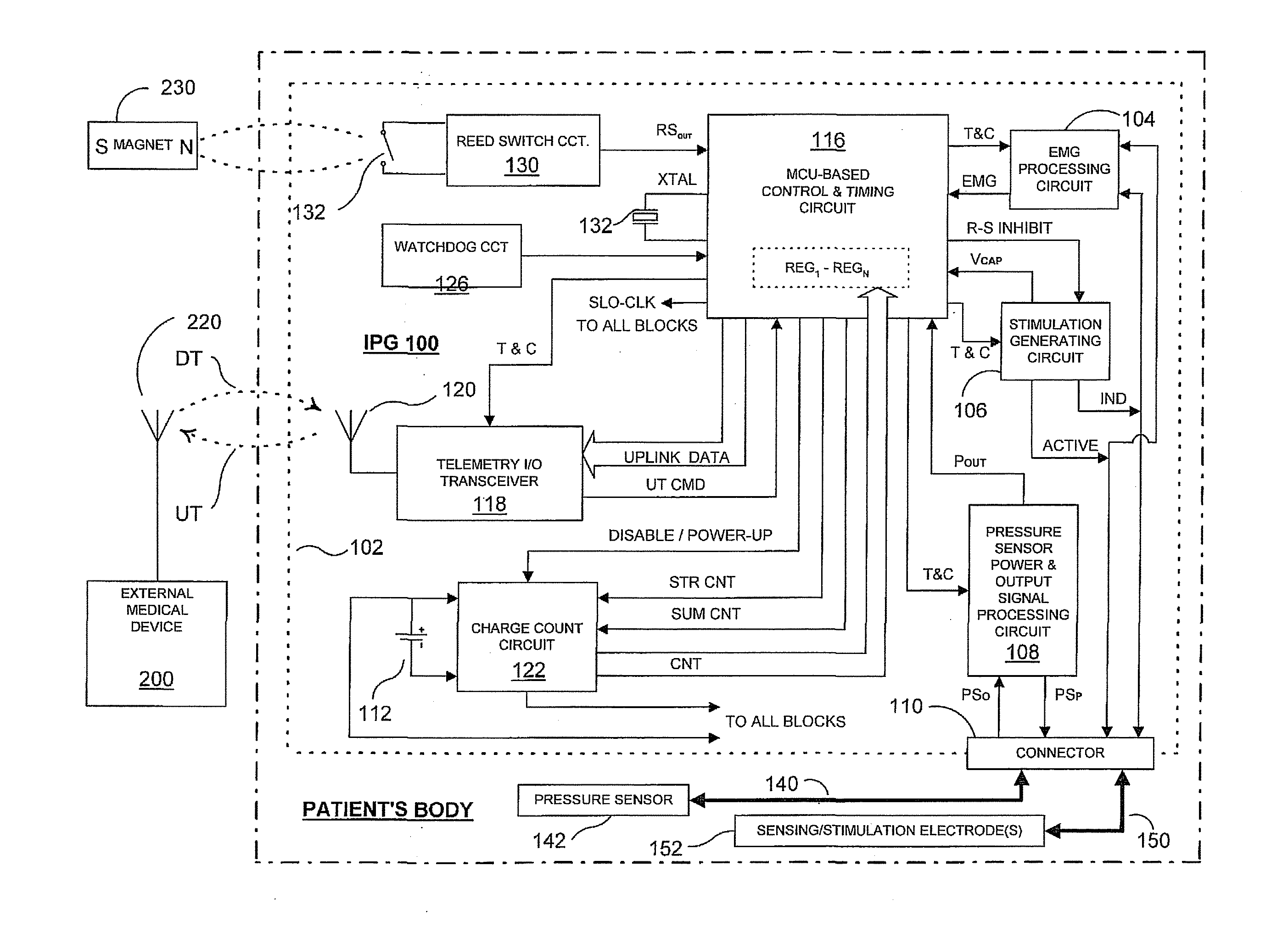
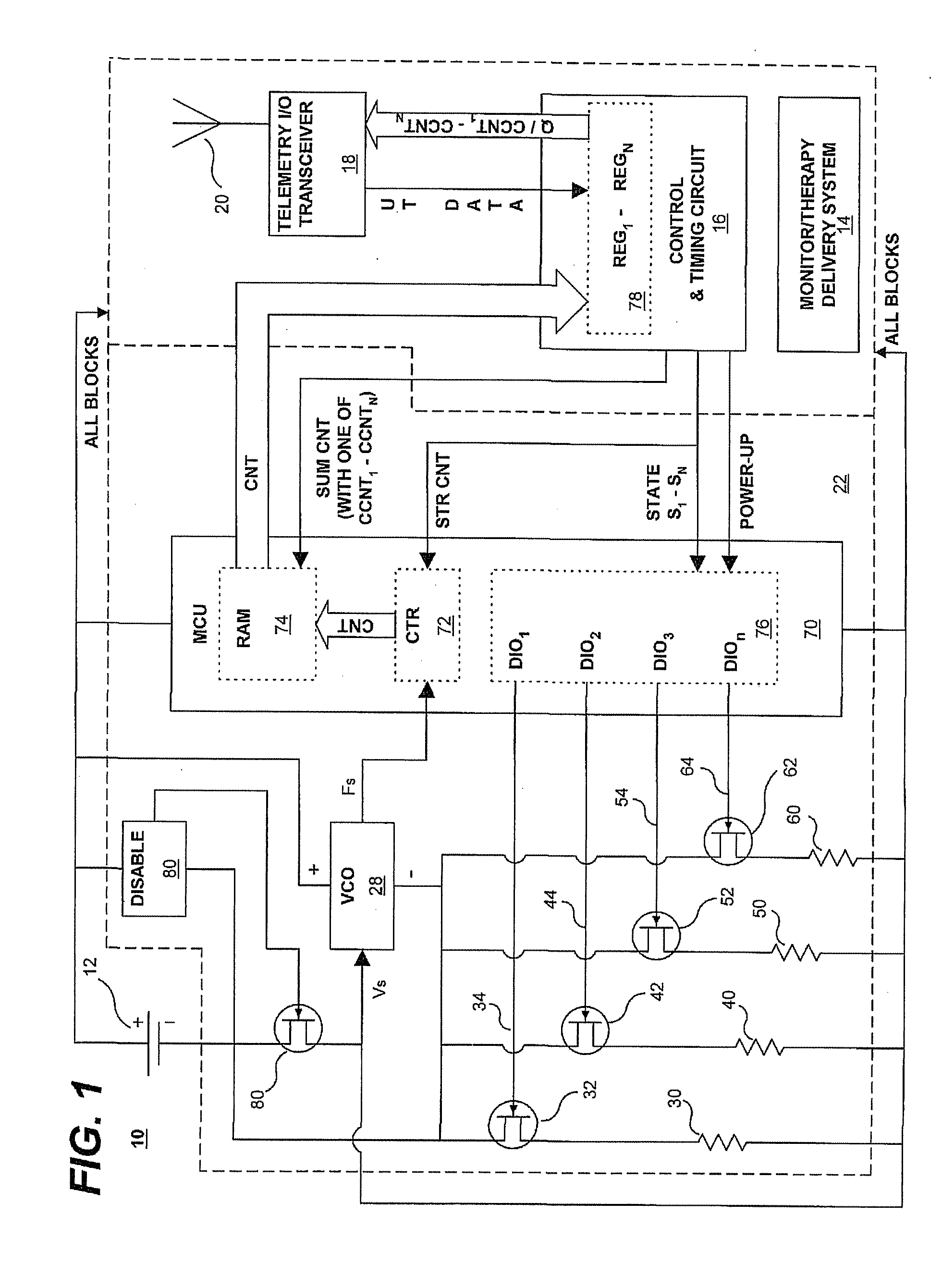
[0026]Thus, in reference to FIG. 1, a battery charge depletion monitor is depicted for monitoring the amount of charge delivered by a battery of an IMD operable in at least first and second current drain states or a plurality of drain states 1, 2, 3, . . . n (where n=4 in this example). For simplicity of illustration, other circuitry and components of a typical IMD 10 that are not involved in the accumulation of battery charge counts for practice of the present invention are not depicted in detail in FIG. 1. Moreover, the IMD 10 is schematically depicted including discre...


PUM


Abstract

A system and method of monitoring the amount of charge consumed from a battery powering a device, e.g., an implantable medical device, operable in at least first and second current drain states are disclosed. In each drain state, a current-sensing resistance correlated to the drain state is connected with the battery to develop a respective current drain state voltage that is converted to a current drain state count established over the duration of the drain state. The first and second current drain state counts are accumulated as cumulative first and second current drain state counts that are indicative of the amount of charge consumed from the battery. A battery charge state may be estimated from the cumulative first current drain state count and the first current state resistance and the cumulative second current drain state count and second current state resistance.

Description

FIELD[0001]The present invention pertains to methods and apparatus for monitoring a battery of a device, particularly the battery of an implantable medical device, enabling estimation of the depletion of and / or the remaining battery charge and remaining battery life.BACKGROUND[0002]As stated in U.S. Pat. Nos. 6,671,552 and 6,901,293, a wide variety of implantable medical devices (IMDs) are commercially released or proposed for clinical implantation that are programmable in a variety of operating modes and are interrogatable using RF telemetry transmissions. Such IMDs include cardiac pacemakers, pacemaker / cardioverter / defibrillators, now referred to as implantable cardioverter-defibrillators (ICDs), cardiomyostimulators, other electrical stimulators including nerve and muscle stimulators, deep brain stimulators, and cochlear implants, drug delivery systems, cardiac and other physiologic monitors, and heart assist devices or pumps, etc. Such IMDs other than monitors and drug delivery ...

Claims


Application Information

Patent Timeline
Patent Type & Authority Applications(United States)
IPC IPC(8): G01R21/00
CPCG01R31/3828G01R31/3648
Inventor VAINGAST, SHAY M.
Owner BOSTON SCI SCIMED INC
Why Eureka
Try Eureka