
Reversible ratchet wrench

a ratcheting wrench and ratcheting technology, applied in the field of ratcheting wrenches, can solve the problems of unreliable ratcheting-direction switching operation between the drive member and the pawl, liable to get stuck or fail to provide reliable switching, and the ratcheting tool malfunction

Active Publication Date: 2007-10-09
HU BOBBY
View PDF4 Cites 45 Cited by
  • Summary
  • Abstract
  • Description
  • Claims
  • Application Information

AI Technical Summary

Benefits of technology

"The present invention is a reversible ratchet wrench that includes a handle, head, drive member, pawl, ring, reversing plate, and switching member. The technical effects of the invention include the ability to change the driving rotating direction of the wrench by moving the reversing plate between two positions corresponding to opposite driving rotating directions, the ability to turn the wrench with a thumb piece, the use of an elastic element to press against the pawl, the use of a retaining means to keep the reversing plate in one of the positions, and the ability to change the position of the wrench with a switching member."

Problems solved by technology

In practice, the transmission member deforms to an excessive extent and, thus, results in unreliable ratcheting-direction switching operation between the drive member and the pawl.
As a result, the switching arrangement is liable to get stuck or fails to provide reliable switching.
Further, the transmission member fatigues easily due to excessive deformation and / or twist under the action of shear forces from the pawl, the ring, the head, and the reversing plate, leading to malfunction of the ratcheting tool.

Method used


Image

  • Reversible ratchet wrench
  • Reversible ratchet wrench
  • Reversible ratchet wrench

Examples


Embodiment Construction

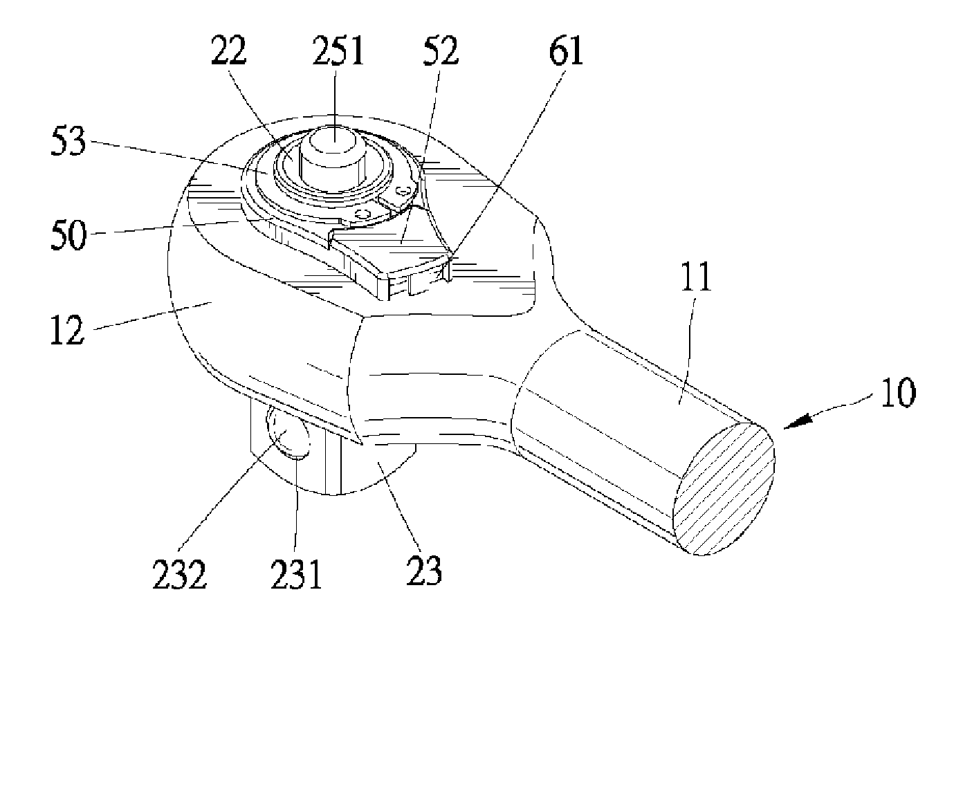
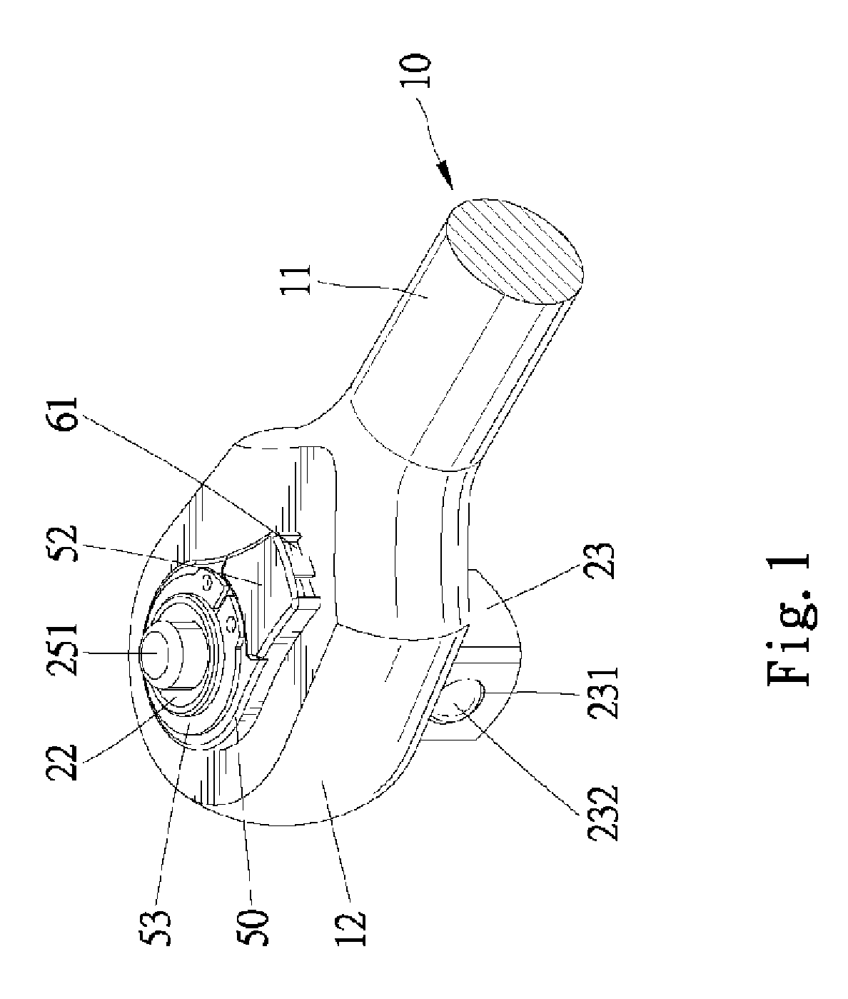
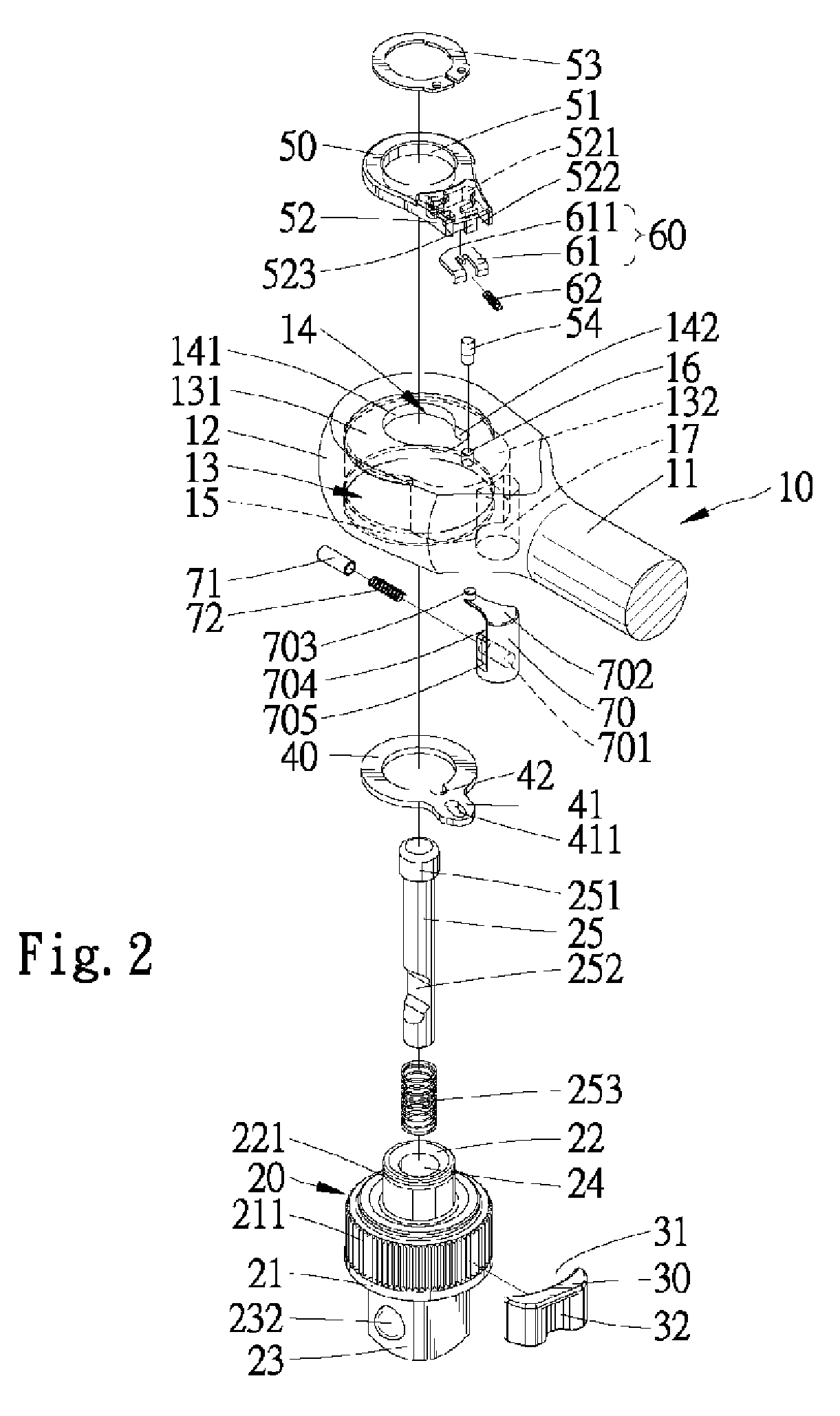
[0031]Referring to FIGS. 1 through 3, a reversible ratchet wrench 10 in accordance with the present invention comprises a handle 11 and a head 12 extending from an end of the handle 11. In this example, the head 12 is substantially circular and has a small volume. The head 12 includes a compartment 13 consisting of a larger, first compartment section 131 and a smaller, second compartment section 132. A top face (not labeled) of the head 12 includes an opening 14 consisting of a substantially circular opening section 141 that is concentric with the first compartment section 131 and a non-circular (substantially rectangular in this example) opening section 142. The top face of the head 12 further includes a pin hole 16 adjacent to the opening section 142. Defined in a bottom face of the head 12 is a circular hole 15 that is concentric with the first compartment section 131 and has a diameter the same as that of the first compartment section 131. Thus, the bottom face of the head 12 is...


PUM


Abstract

A reversible ratchet wrench includes a handle from which a head extends. The head includes a compartment and a receiving hole in communication with the compartment. A drive member is rotatably mounted in the compartment and a pawl is slidably mounted in the compartment. A ring is mounted in the compartment and around an end of the drive member. A reversing plate is pivotably mounted to the end of the drive member and operatively connected to the ring to turn therewith. A switching member is pivotably mounted in the receiving hole of the head. The switching member is operatively connected to a tip piece of the ring to turn therewith. The switching member is operatively connected to the pawl to move the pawl for changing a driving rotating direction of the reversible ratchet wrench when the reversing plate is moved between two positions corresponding to two opposite driving rotating directions.

Description

BACKGROUND OF THE INVENTION[0001]1. Field of the Invention[0002]The present invention relates to a ratchet wrench and, more particularly, to a reversible ratchet wrench.[0003]2. Description of the Related Art[0004]U.S. Pat. No. 6,431,031 discloses a reversible ratcheting tool comprising a handle, a head on an end of the handle, a drive member, a pawl, a ring, and a reversing plate. A transmission member in the form of a spring is mounted between the reversing plate and the pawl to covert manual pivotal movement of the reversing plate into pivotal movement of the pawl. The ratcheting tool of this design has a smaller head while providing higher torque-bearing capacity. In practice, the transmission member deforms to an excessive extent and, thus, results in unreliable ratcheting-direction switching operation between the drive member and the pawl. As a result, the switching arrangement is liable to get stuck or fails to provide reliable switching. Further, the transmission member fati...

Claims


Application Information

Patent Timeline
Patent Type & Authority Patents(United States)
IPC IPC(8): B25B13/46B25B13/00B25B17/00
CPCB25B13/463
Inventor HU, BOBBY
Owner HU BOBBY
Learn More