
Method and foot switch control for fast angulation changes in an x-ray system

a technology of x-ray system and angulation change, which is applied in the direction of electrical equipment, medical science, diagnostics, etc., can solve the problems of difficult for physicians to accurately position the x-ray system in space to generate a two-dimensional image that captures all of the desired information, and the system is significantly more expensive than the monoplane system. , the view is limited, and the effect of reducing the difficulty of the physician

Active Publication Date: 2007-11-22
SIEMENS HEALTHCARE GMBH
View PDF12 Cites 16 Cited by
  • Summary
  • Abstract
  • Description
  • Claims
  • Application Information

AI Technical Summary

Benefits of technology

[0014] It is an object of the present invention to simplif

Problems solved by technology

Monoplane systems, however, can supply only two-dimensional images, and therefore correctly positioning the x-ray system in space to generate a two-dimensional image that captures all of the desired information can be difficult for the physician.
These systems, however, are significantly more expensive than monoplane systems.
Moreover, the view is limited to two viewing directions, and access to the patient is made more difficult by the presence of the second x-ray system.

Method used


Image

  • Method and foot switch control for fast angulation changes in an x-ray system
  • Method and foot switch control for fast angulation changes in an x-ray system
  • Method and foot switch control for fast angulation changes in an x-ray system

Examples


Embodiment Construction

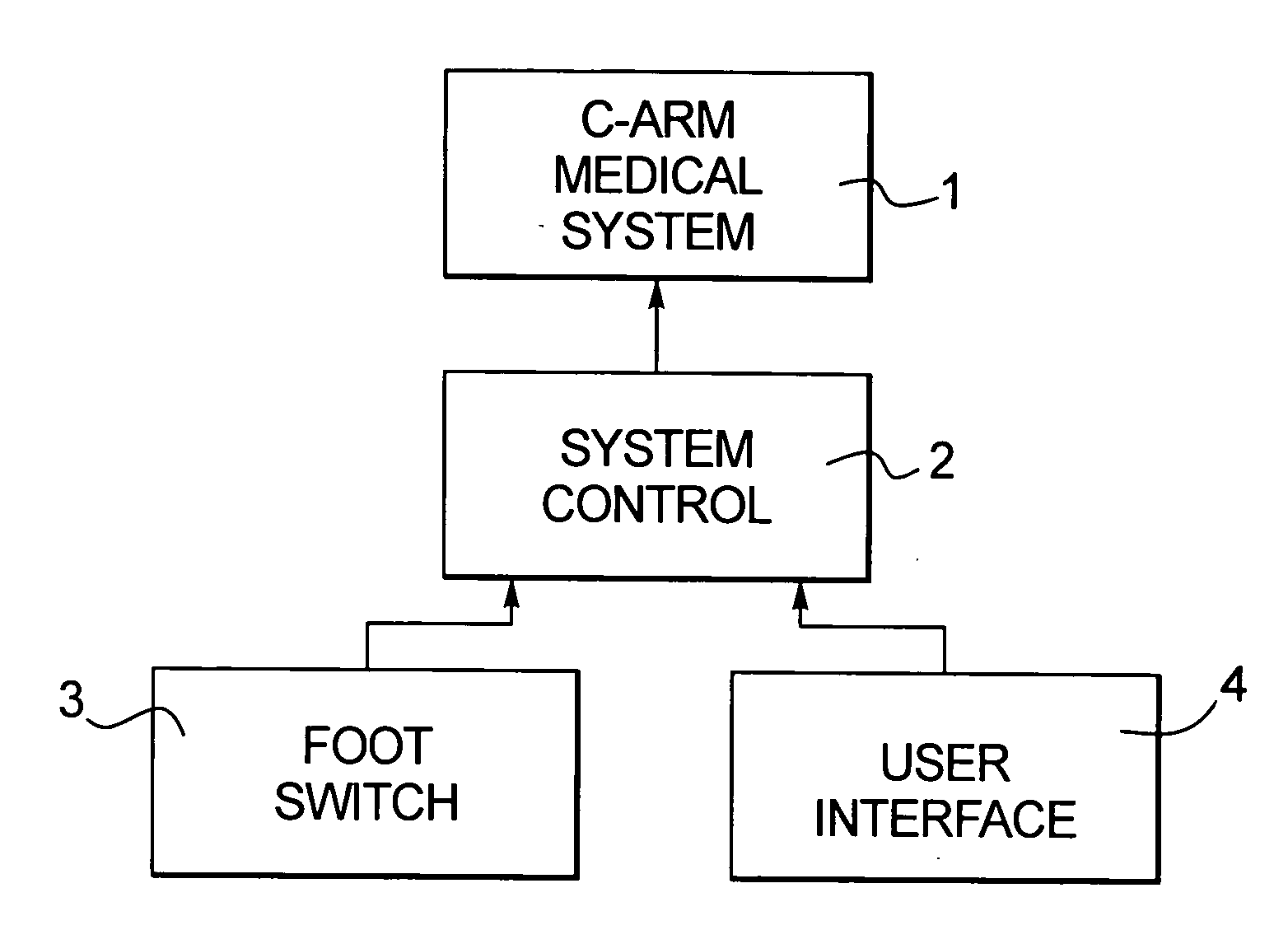
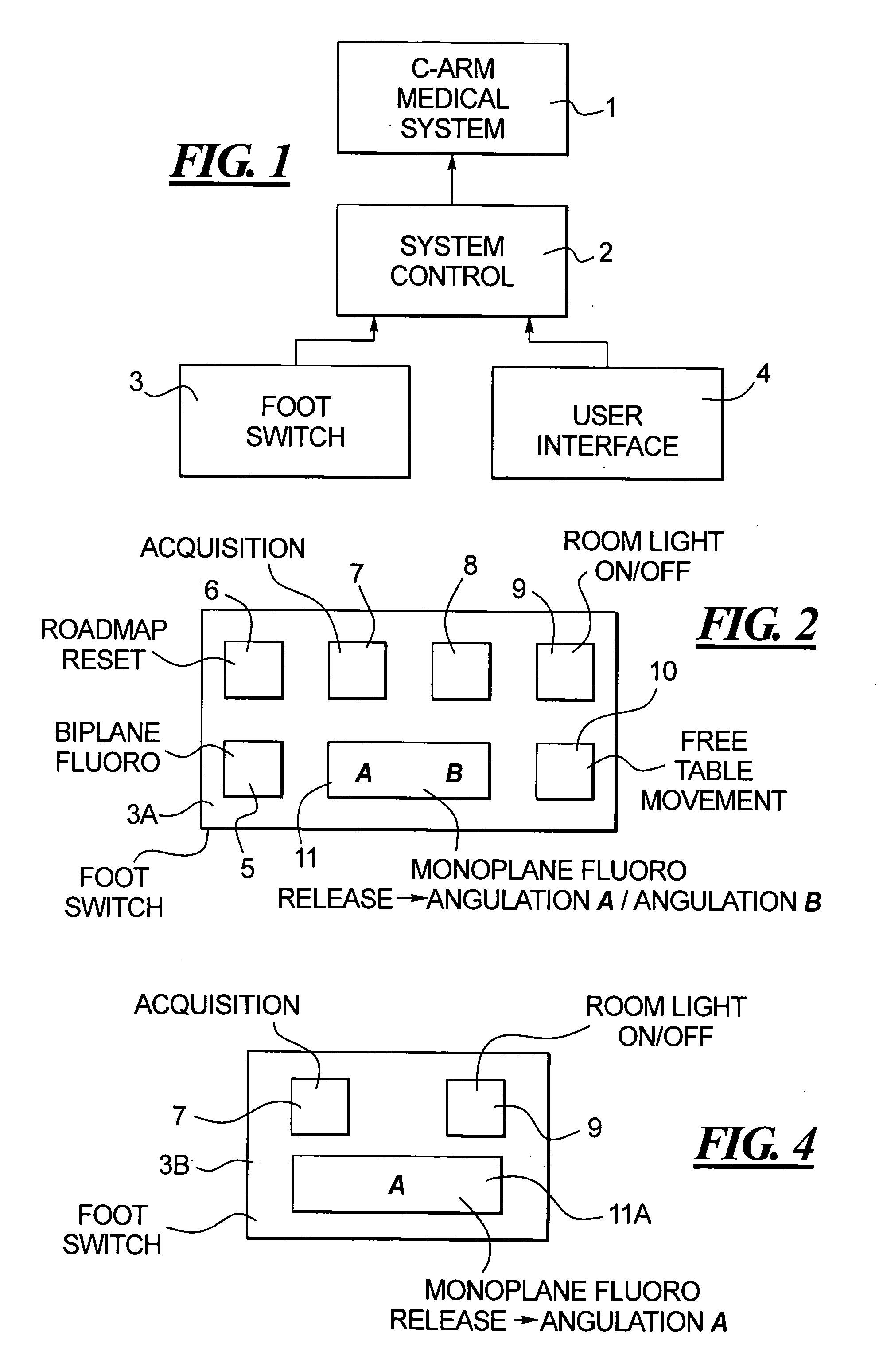
[0024]FIG. 1 illustrates the basic components for operating a medical system 1 in accordance with the present invention. The medical system 1 may be, for example, a biplane angiography system. The medical system 1 is operated by a computerized system control, to which operating commands can be provided via a flip switch 3 and a separate user interface 4, such a keyboard, mouse, touch display, etc.

[0025] A first embodiment of the foot switch 3A in accordance with the invention is shown in FIG. 2. This embodiment of the foot switch 3A has a conventional arrangement of foot pedals, that include a food pedal 5 for biplane fluoro, a foot pedal 6 for roadmap reset, a foot pedal 7 for image acquisition that, when depressed, triggers emission of x-rays, a foot pedal 8 that can be used or not used as needed, a foot pedal 9 that controls the room light (on / off), and a foot pedal 10 that freeze (releases or enables) movement of the table on which the patient is lying.

[0026] A foot switch of ...


PUM


Abstract

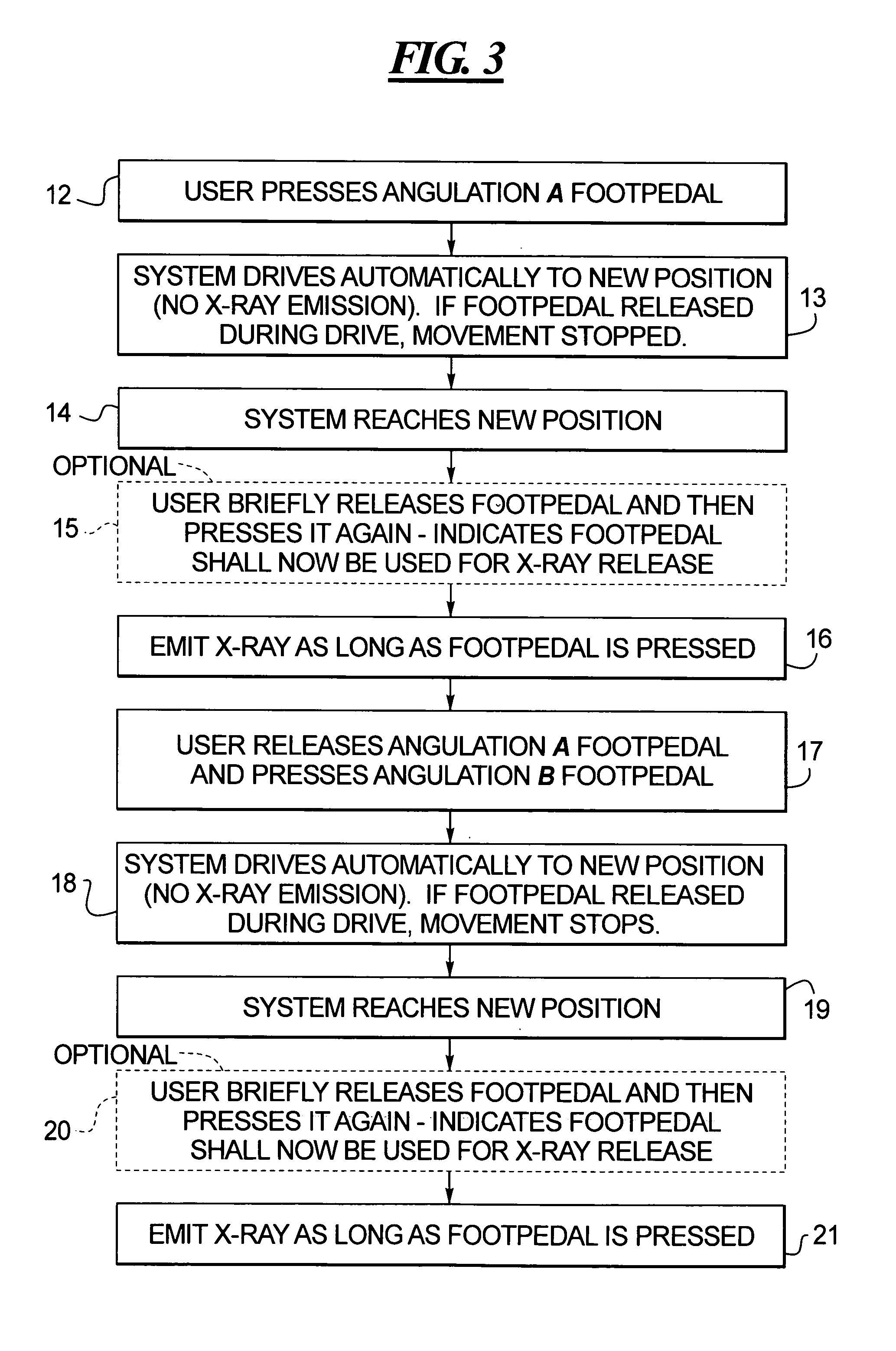
In a method for fast angulation changes in a C-arm x-ray system, and a foot switch for effecting such fast angulation, a pedal of the foot switch that normally has a function not related to angulation of the C-arm is either permanently, or temporarily programmed, to operate as a pedal that, when depressed, automatically moves the C-arm to a predetermined angulation. The pedal can be movable between two positions, in order to selectively, automatically move the C-arm to either of two predetermined angulation positions, or can be used in conjunction with another pedal for that purpose. The pedal can also be temporarily given a security function and / or a radiation triggering function.

Description

BACKGROUND OF THE INVENTION [0001] 1. Field of the Invention [0002] The present invention relates to a method for effecting fast angulation changes of the C-arm of an x-ray system, as well as to a foot switch control for effecting such fast angulation changes. [0003] 2. Description of the Prior Art [0004] X-ray systems are commonly used for medical diagnostic purposes as well as medical interventional procedures that have an x-ray source (x-ray tube) that emits x-ray radiation that penetrates an examination subject and is detected by a radiation detector disposed opposite to the x-ray source. The x-ray source and the radiation detector are movable relative to the patient, such as by being mounted on a rotatable C-arm or some other type of movement-facilitating mechanism. The angle that a center ray, emitted by the x-ray source and proceeding to the radiation detector, makes with respect to a predetermined axis, usually the vertical axis, is defined as the angulation of the x-ray sys...

Claims


Application Information

Patent Timeline
IPC IPC(8): H05G1/56
CPCA61B6/542A61B6/4441
Inventor SANDKAMP, BERNHARDBOCSE, JAN
Owner SIEMENS HEALTHCARE GMBH
Learn More