Turbomolecular pump

a technology of molecular pump and pump body, which is applied in the direction of non-positive displacement pumps, motors, liquid fuel engines, etc., can solve the problems of increasing the number of pump components. , to achieve the effect of reducing manufacturing costs, simplifying the pump assembly, and reducing the number of pump components

Inactive Publication Date: 2007-10-09
PFEIFFER VACUUM GMBH
View PDF14 Cites 4 Cited by
  • Summary
  • Abstract
  • Description
  • Claims
  • Application Information

AI Technical Summary

Benefits of technology

[0011]The present invention permits to substantially reduce the number of pump components which reduces manufacturing costs and simplifies the pump assembly. The spacer rings are so connected with each other that they take over the function of the pump housing of securing the stator discs in place and centering the same. The other functions of the housing are taken over by sections of the recipient which is to be pumped out. This ensures an optimal adaptation of the pump and the recipient. As a result, it becomes possible to arranged the pumping active components in an immediate vicinity of an evacuation region. Because the spacer rings takeover of the functions of the pump housing, the housing as a separate component is eliminated.

Problems solved by technology

The drawback of the turbomolecular pump of the type disclosed in the German Patent consists in a large number of components which makes the construction of the pump rather complicated.
Moreover, the pump has a rather rigid construction which makes the adaptation of the pump to the requirements of a particular usage rather difficult.
However, a drawback of this construction consists in that additional parts are needed for securing and holding together separate stator components.
The use of additional parts complicates the assembly of the turbomolecular pump and require additional space.

Method used


Image

  • Turbomolecular pump
  • Turbomolecular pump
  • Turbomolecular pump

Examples


Embodiment Construction

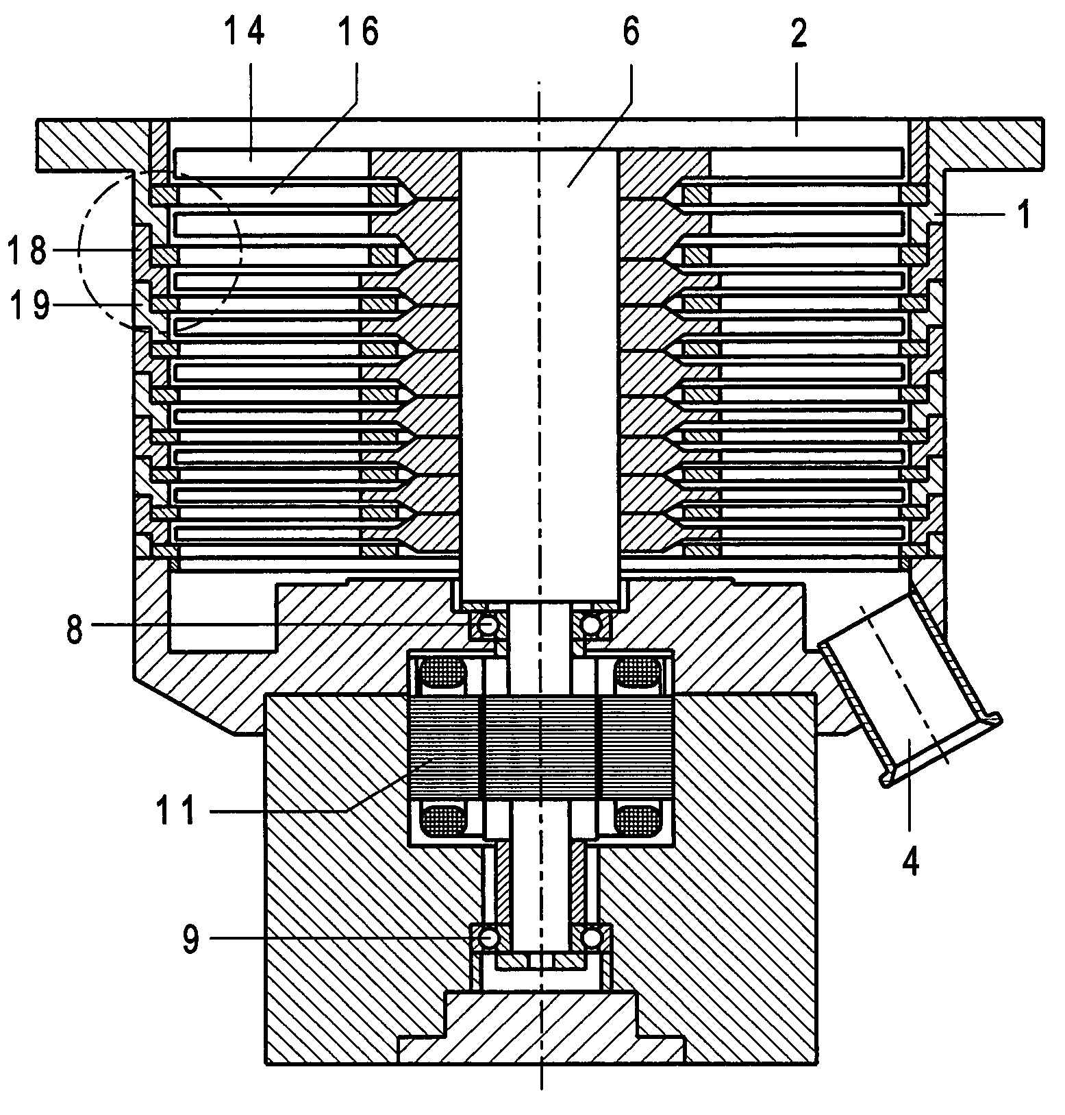
[0019]A turbomolecular pump according to the present invention, which is shown in FIG. 1, has a housing 1 formed of spacer rings 18 and having a suction inlet opening 2 and a gas outlet opening 4. A rotor shaft 6 is supported in bearings 8 and 9 and is driven by a motor 11. A plurality of rotor discs 14 is secured on the rotor shaft 6. Stator discs 16 are arranged between the rotor discs 14 and are retained at a distance from each other by the spacer rings 18. The rotor discs 14 and the stator discs 16 are provided with a pumping active structure and together produce a pumping effect.

[0020]According to the present invention, the spacer rings 18 are assembled and connected with each other in such a way that they form the housing 1 of the pump. The spacer rings 18 are also used for securing and centering the stator discs 16.

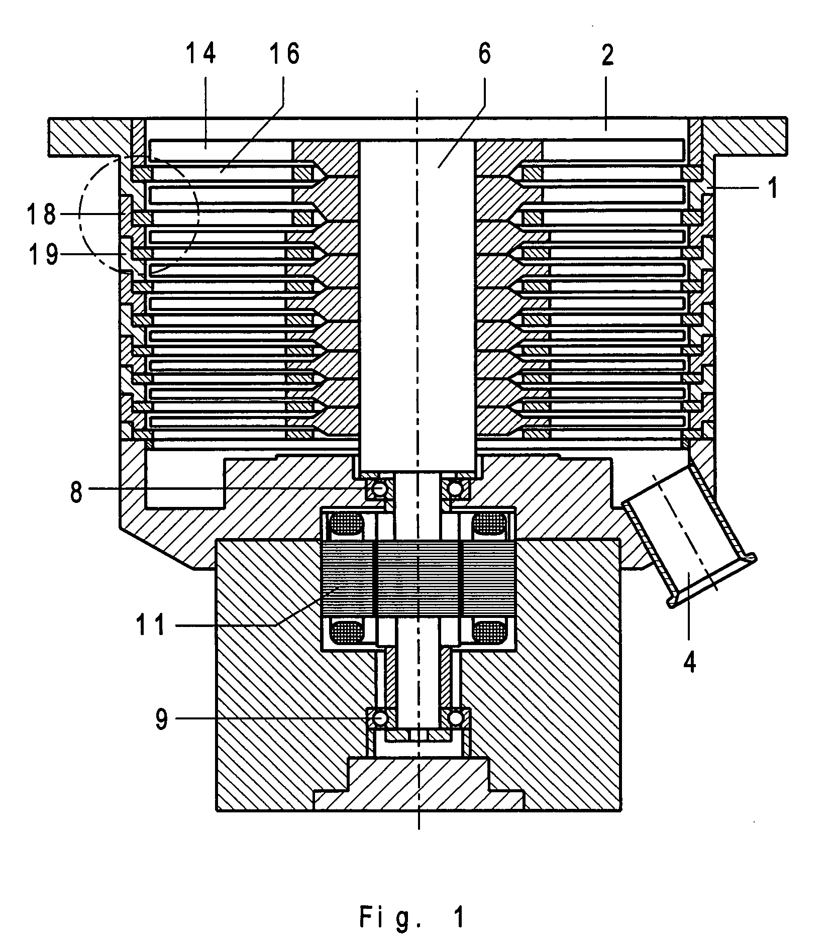
[0021]FIG. 2 shows two spacer rings 18a and 19a for securing a stator disc 16. At a location 20, the two rings are connected with each other by thread means.
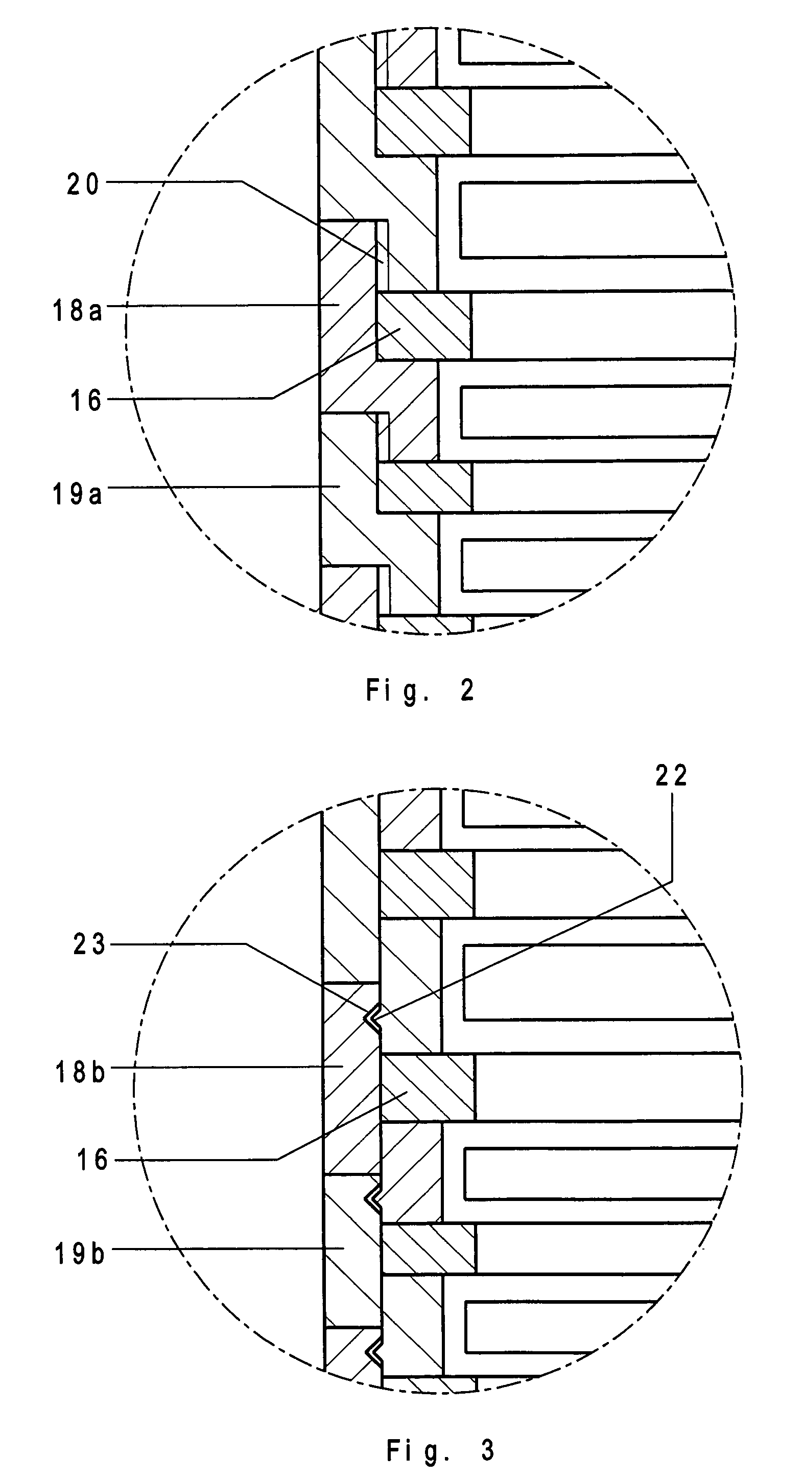
[0022]...


PUM


Abstract

A turbomolecular pump includes a plurality of rotor and stator discs arranged alternatively one behind another and producing together a pumping effect, a plurality of spacer rings for retaining the stator discs at a distance from each other; and connection elements for fixedly connecting adjacent spacer rings with each other, so that the spacer rings together provide for securing and centering of the stator discs, taking over the function of a pump housing that is eliminated.

Description

BACKGROUND OF THE INVENTION[0001]1. Field of the Invention[0002]The present invention relates to a turbomolecular pump including a plurality of rotor and stator discs arranged alternatively one behind another and producing together a pumping effect, and a plurality of spacer rings for retaining the stator discs at a distance from each other.[0003]2. Description of the Prior Art[0004]The pump of the type discussed above has pumping active elements formed of rotor and stator discs provided with vanes and arranged alternatively one behind another. The rotor and stator discs generally are provided each with a support ring with vanes provided on the ring outer sides. The vanes, which are provided on the rotor discs rotate with a high speed and produce, together with the stator vanes, the pumping effect. The stator discs are retained at a distance from each other with spacer rings arranged at outer circumferences of the stator discs. The distance between separate stator discs is so select...

Claims


Application Information

Patent Timeline
Patent Type & Authority Patents(United States)
IPC IPC(8): F04D29/40F04D19/04F04D29/54
CPCF04D29/542F04D19/042
Inventor STANZEL, JOERG
Owner PFEIFFER VACUUM GMBH
Why Eureka
Try Eureka