
Method for resolving phase in electronic speckle interferometry

a technology of electronic speckle pattern and phase resolution, applied in the direction of force measurement, force measurement, force measurement by measuring optical property variation, etc., can solve the problem of computational burden of all such methods

Active Publication Date: 2007-10-09
SOUTHEASTERN LOUISIANA UNIVERSITY
View PDF5 Cites 11 Cited by
  • Summary
  • Abstract
  • Description
  • Claims
  • Application Information

AI Technical Summary

Problems solved by technology

All such methods are computationally burdensome.
In addition, they require multiple images be taken, therefore are not applicable to applications where the deformation is continuous because the phase change to be evaluated varies when the extra images are taken.

Method used


Image

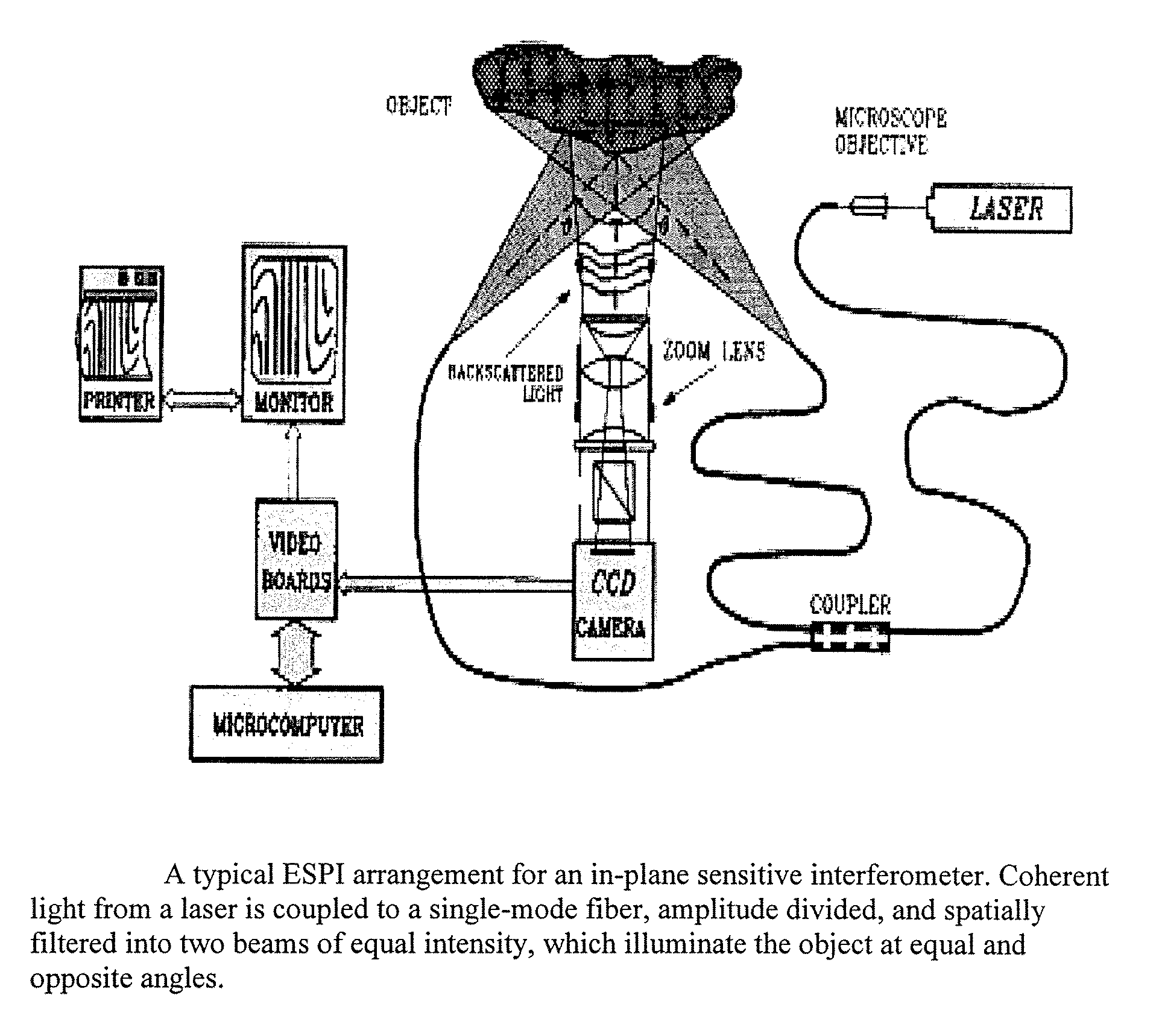
  • Method for resolving phase in electronic speckle interferometry
  • Method for resolving phase in electronic speckle interferometry
  • Method for resolving phase in electronic speckle interferometry

Examples


Embodiment Construction

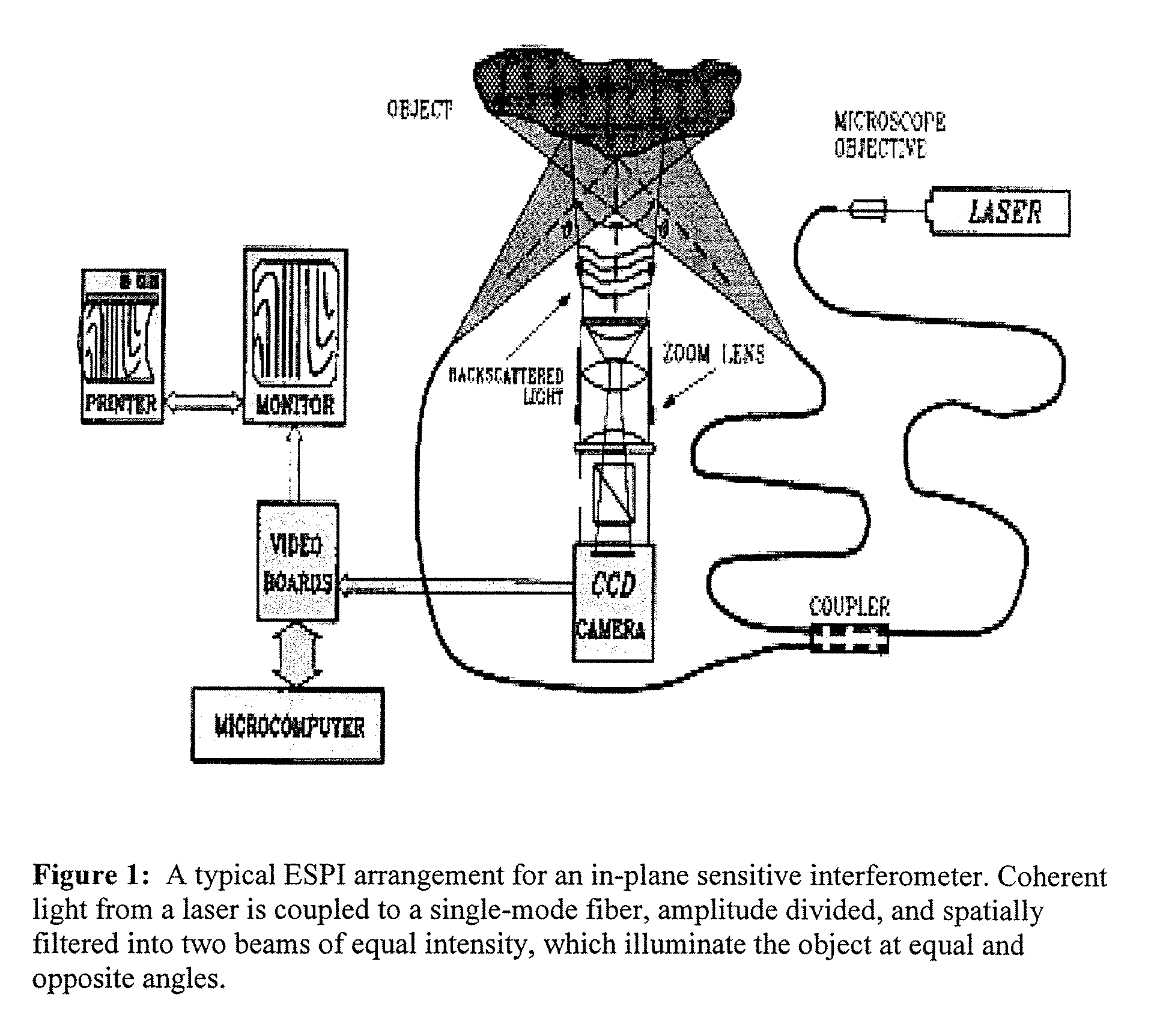
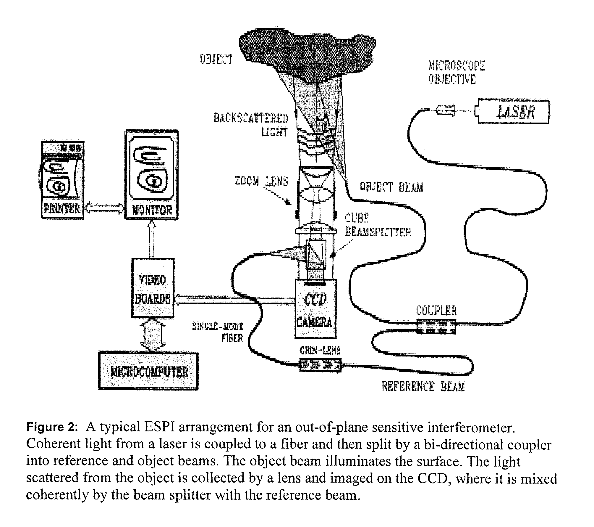
[0012]The invention is a procedure to determine the phase of a perturbed object in an interferomic device. The invention can be used for both in-pane and out-of-plane interferometry. The following notation will be used.[0013]I(x,y) is the measured output beam intensity of the non-deformed object, as measured on the in-plane interferogram by means of the imaging system such has an array of pixels having individual intensities and each having corresponding respective transverse coordinates (x,y); (note, “non-deformed” refers to the lack of a later deformation or movement; for instance if three frames are recorded, F1, F2 and F3 at different times; F1 is a non-deformed frame with respect to F2 and F3; while F2 is a non-deformed frame only with regards to the later deformed frame, F3).[0014]Id (x,y) is the output beam intensity of the perturbed (henceforth considered a deformation) object[0015]I1 (x,y) is the beam intensity measured on one arm of the device, and I2 (x,y) is the beam int...


PUM


Abstract

The invention is a method of determining the phase difference between two interferometric images. The method includes the steps of measuring the intensities of the two beam arms, and measuring the intensities of the interfering beam arms at two different times (two frames). From the recorded data, the phase angle between the arms can be determined for each frame. These frame phase angles subtracted, and the sine of the difference is taken. The resulting data set is examined to determine a multiplicative factor that converts the minimum and maximum to the bounds of the sine function (−1, +1). This multiplicative factor is applied to a bounded trig function of the difference of the frame angles, and the inverse of the bounded trig function is taken, resulting in the phase difference between frames.

Description

FIELD OF THE INVENTIONThe invention relates to electronic speckle pattern interferometry and in particular to methods of determining phase from a speckle image comparison.BACKGROUND OF THE INVENTION[0001]Optical path length measurements, made by interferometry, are highly sensitive and adaptable to the study of a wide range of physical phenomena because they sensitively measure small changes in the optical path length induced by physical process, of the order of a fraction of an optical wavelength.[0002]Optical path length variations may be induced in the distance between a point on the surface of an object and the corresponding point on the image plane formed by an imaging system used to make an image of the object in the presence of externally applied perturbations. A number of physical and chemical phenomena provide mechanisms for inducing spatial distribution in such changes of the optical path length that may then be interferometrically probed. Such mechanisms could include the...

Claims


Application Information

Patent Timeline
IPC IPC(8): G01B9/02
CPCG01B11/162G01B9/02095G01B9/02083G01B9/02098
Inventor YOSHIDA, SANICHIRO
Owner SOUTHEASTERN LOUISIANA UNIVERSITY
Learn More