Brake structure for a roll-up door

a technology for a brake structure and a roll-up door, which is applied in the direction of braking systems, door/window protective devices, hoisting equipment, etc., can solve the problems of not being able the roll-up door of iron cannot be released from the brake state, and fire still occasionally occurs, so as to prevent fire from spreading

Inactive Publication Date: 2007-10-16
ANCHUAN CORP
View PDF8 Cites 32 Cited by
  • Summary
  • Abstract
  • Description
  • Claims
  • Application Information

AI Technical Summary

Benefits of technology

[0009]Accordingly, an object of the present invention is to provide a brake structure for a roll-up door which can be released from a brake state to close doorway when fire and power cut take place thereby preventing fire from spreading.

Problems solved by technology

However, fire still occasionally takes place.
However, when no electricity can be supplied to the AC solenoid 20, such as when fire and power cut take place at the same time, the iron roll-up door cannot be released from the brake state and so cannot prevent fire from spreading.

Method used


Image

  • Brake structure for a roll-up door
  • Brake structure for a roll-up door
  • Brake structure for a roll-up door

Examples


Embodiment Construction

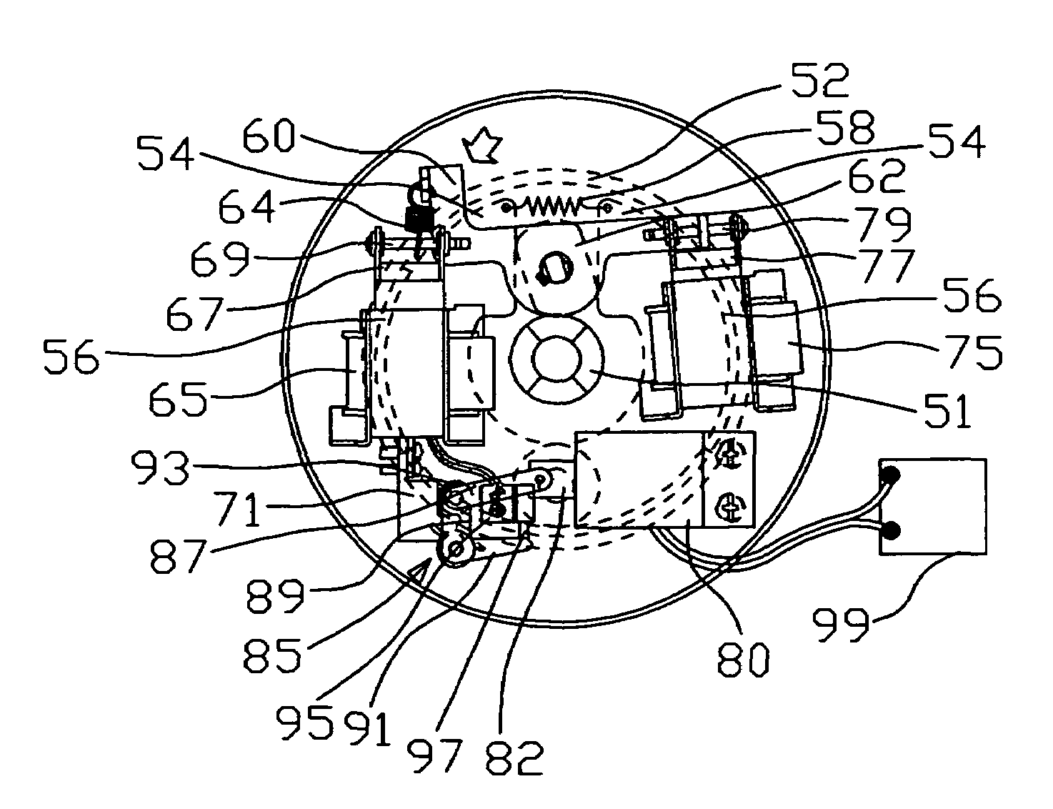
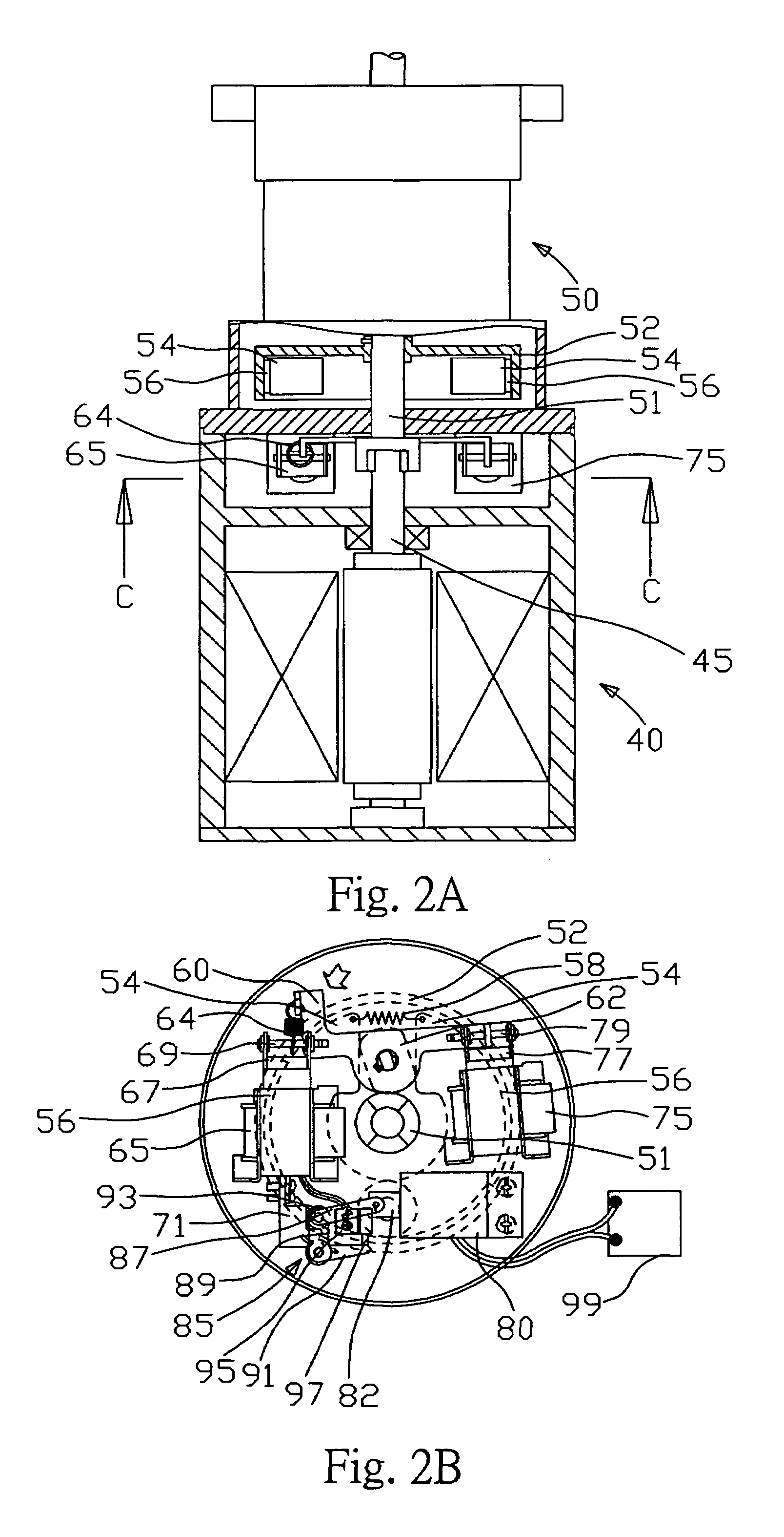
[0022]Referring to FIGS. 2A and 2B, a transmission structure of an iron roll-up door includes a motor 40 and a speed reducer 50. A rotation shaft 45 of the motor 40 is connected to a transmission shaft 51 of the speed reducer 50. The motor 40 is positioned at the top of the speed reducer 50. The rotation of the rotation shaft 45 of the motor 40 drives the transmission shaft 51 of the speed reducer 50 to rotate. The rotation of the transmission shaft 51 is decelerated through the speed reducer 50 to drive the roll-up door to open or close. A brake structure of the present invention is formed at the front of the speed reducer 50. The brake structure includes a brake drum 52. The transmission shaft 51 of the speed reducer 50 extends through and is connected to the brake drum 52 whereby the brake drum 52 and the transmission shaft 51 synchronally rotate. A pair of brake shoes 54 is received in opposite inner sides of the brake drum 52. Each brake shoe 54 is generally C-shaped and faces ...


PUM


Abstract

A brake structure for a roll-up door includes a brake drum fixed to a transmission shaft of a speed reducer. The brake drum receives a pair of brake shoes in opposite inner sides thereof. The brake shoes are pivotably connected to each other at an end of each brake shoe. A linking resilient member is connected between the free ends of the brake shoes. A brake pad is attached to a surface of each brake shoe facing the inner surface of the brake drum. A controlling lever is disposed at the top of the speed reducer corresponding to the free ends of the brake shoes. One end of the controlling lever is connected to an end of a fixing resilient member. The other end of the fixing resilient member is connected to a moving iron of a first solenoid. A clasping block is connected to the moving iron of the first solenoid. The other end of the controlling lever is connected to a moving iron of a second solenoid. A controlling block is disposed at the controlling lever between the free ends of the brake shoes and in contact to the free ends of the brake shoes. A brake control solenoid is disposed at the top of the speed reducer. The brake control solenoid is connected to a power supply with capacitance character. A moving iron of the brake control solenoid is connected to a connecting rod mechanism. The clasping block is connected to the connecting rod mechanism.

Description

BACKGROUND OF THE INVENTION[0001]1. Field of the Invention[0002]The present invention relates to a brake structure for a roll-up door, and particularly to a brake structure which is released to close a doorway through a roll-up door when fire and power cut take place in a building.[0003]2. Prior Art[0004]It is important to prevent fire from taking place at a building. However, fire still occasionally takes place. So it is also important to prevent fire from spreading when fire takes place. Iron roll-up doors are widely used in public occasions as fireproofing separation thereby preventing fire from spreading during fire.[0005]Referring to FIGS. 1A and 1B, a conventional brake structure for an iron roll-up door includes a brake drum 12 attached in a speed reducer 10. A transmission shaft 14 of the speed reducer 10 extends through and is connected to the brake drum 12, whereby the brake drum 12 and the transmission shaft 14 rotate synchronally. A pair of brake shoes 16 is received in ...

Claims


Application Information

Patent Timeline
Patent Type & Authority Patents(United States)
IPC IPC(8): F16D65/36F16D65/28E06B9/82F16D65/14F16D65/18
CPCE06B9/82F16D51/18F16D2127/008F16D2121/22
Inventor HSIEH, CHUNG-JUNG
Owner ANCHUAN CORP
Why Eureka
Try Eureka