Adjustable mount for vacuum cup with offset mounting post and swivel

a technology of offset mounting and vacuum cup, which is applied in the direction of load-engaging elements, thin material handling, joints, etc., can solve the problems of adding significantly to the cost and complexity of the system

Active Publication Date: 2007-10-16
DELAWARE CAPITAL FORMATION INC
View PDF24 Cites 44 Cited by
  • Summary
  • Abstract
  • Description
  • Claims
  • Application Information

AI Technical Summary

Benefits of technology

[0006]The present invention provides a material handling system that is operable to move two or more devices or vacuum cups into engagement with an object and to pick up and move the object to a targeted or desired location. The material handling system may move one of the devices or vacuum cups into engagement with the object, and may move a mounting collar of the device along a post as the system moves the other vacuum cup or cups further downward and into engagement with the object. The devices thus may adapt to varying surfaces and surface angles of the objects to be picked up, without requiring controls and independently actuatable cylinders and the like.
[0015]The proximity or thickness of an object at the cup of the pivotable cup assembly may be sensed via an object sensor positioned at a generally central region of the cup of the pivotable cup assembly. The swivel member may have a diameter that is substantially similar to the diameter of the perimeter seal of the cup of the pivotable cup assembly. The swivel joint, or the opposing surfaces of the swivel member and receiving collar, may be substantially near to or in close proximity with the perimeter seal of the cup of the pivotable cup assembly, such that the pivot axis is generally at or near to the vacuum cup and spaced a relatively short distance above the perimeter seal of the vacuum cup. Such a configuration limits or substantially precludes tipping or tilting of the vacuum cup of the material handling device away from the object as it is moved toward and into engagement with the object. Preferably, the pivot axis is within a distance from the perimeter seal that is less than the radius of the perimeter seal of the vacuum cup.
[0016]Therefore, the present invention provides a material handling system that moves multiple material handling devices and vacuum cups into engagement with an object. The object surface may be oriented at an angle or tilt, such that one of the vacuum cups may engage the object before the other vacuum cup engages the object. The material handling system may move the other material handling device and vacuum cup further and into engagement with the object while the mounting collar of the first material handling device is correspondingly moved or slid along the post of the first material handling device. The material handling system and devices of the present invention thus may engage and move objects with varying surfaces without requiring independently operable cylinders and the like.
[0017]By urging and moving the vacuum cup via attachment around a perimeter of the vacuum cup and in close proximity to the vacuum cup, the receiving collar of the support assembly of the present invention provides enhanced sealing of the vacuum cup to the object surface. Such a mounting arrangement limits or substantially precludes tipping or tilting of the vacuum cup of the material handling device away from the object as the vacuum cup is moved into engagement with an angled surface. As the vacuum cup of the material handling device of the present invention is moved into engagement with an object surface, the vacuum cup and perimeter seal pivot about an axis through the receiving collar to align with the angled surface. The pivot axis is generally at or near to the vacuum cup and spaced a relatively short distance above the perimeter seal of the vacuum cup, so that tipping or tilting of the vacuum cup away from the object is limited or substantially precluded. Also, by providing the support post at the receiving collar in a location that is spaced from a generally central axis of the aperture in the receiving collar, the cup assembly of the present invention provides space for the object sensor to be positioned at the generally central region of the vacuum cup and receiving collar, while providing enhanced pivotal movement of the vacuum cup and swivel member relative to the receiving collar and post.

Problems solved by technology

Although such a system may accommodate variations in the surface of the object, the system may include control circuitry and multiple actuators, which may add significantly to the cost and complexity of the system.

Method used


Image

  • Adjustable mount for vacuum cup with offset mounting post and swivel
  • Adjustable mount for vacuum cup with offset mounting post and swivel
  • Adjustable mount for vacuum cup with offset mounting post and swivel

Examples


Embodiment Construction

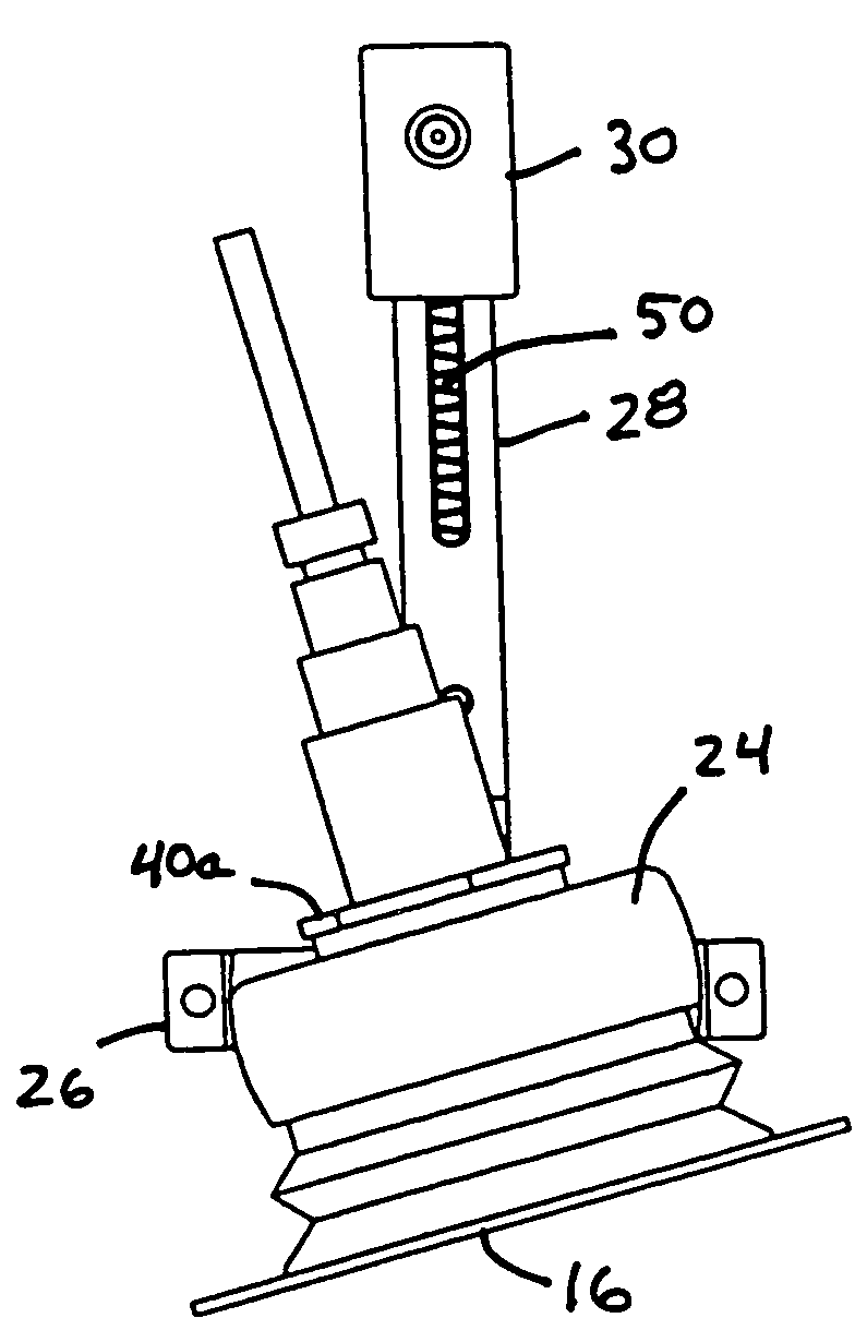
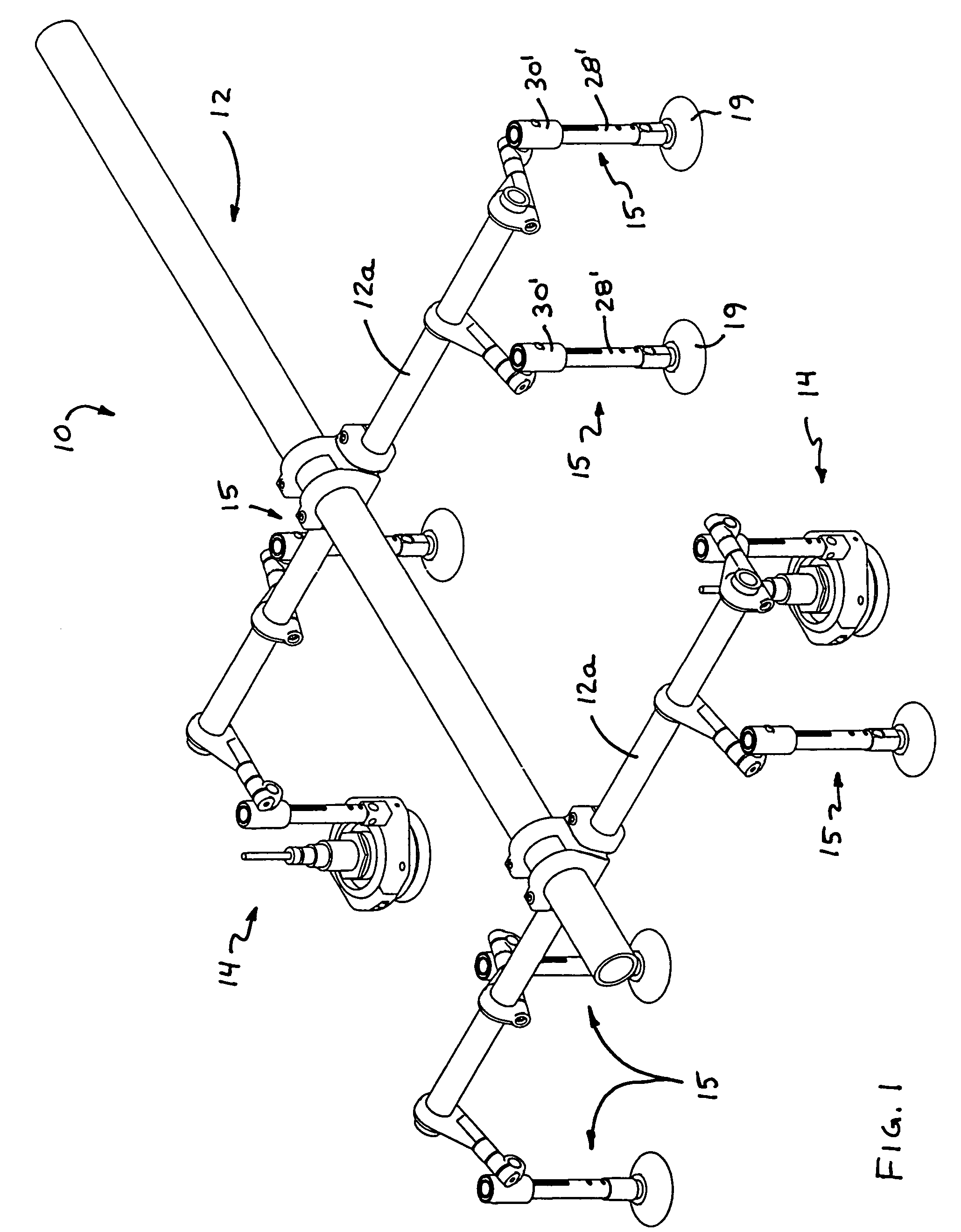
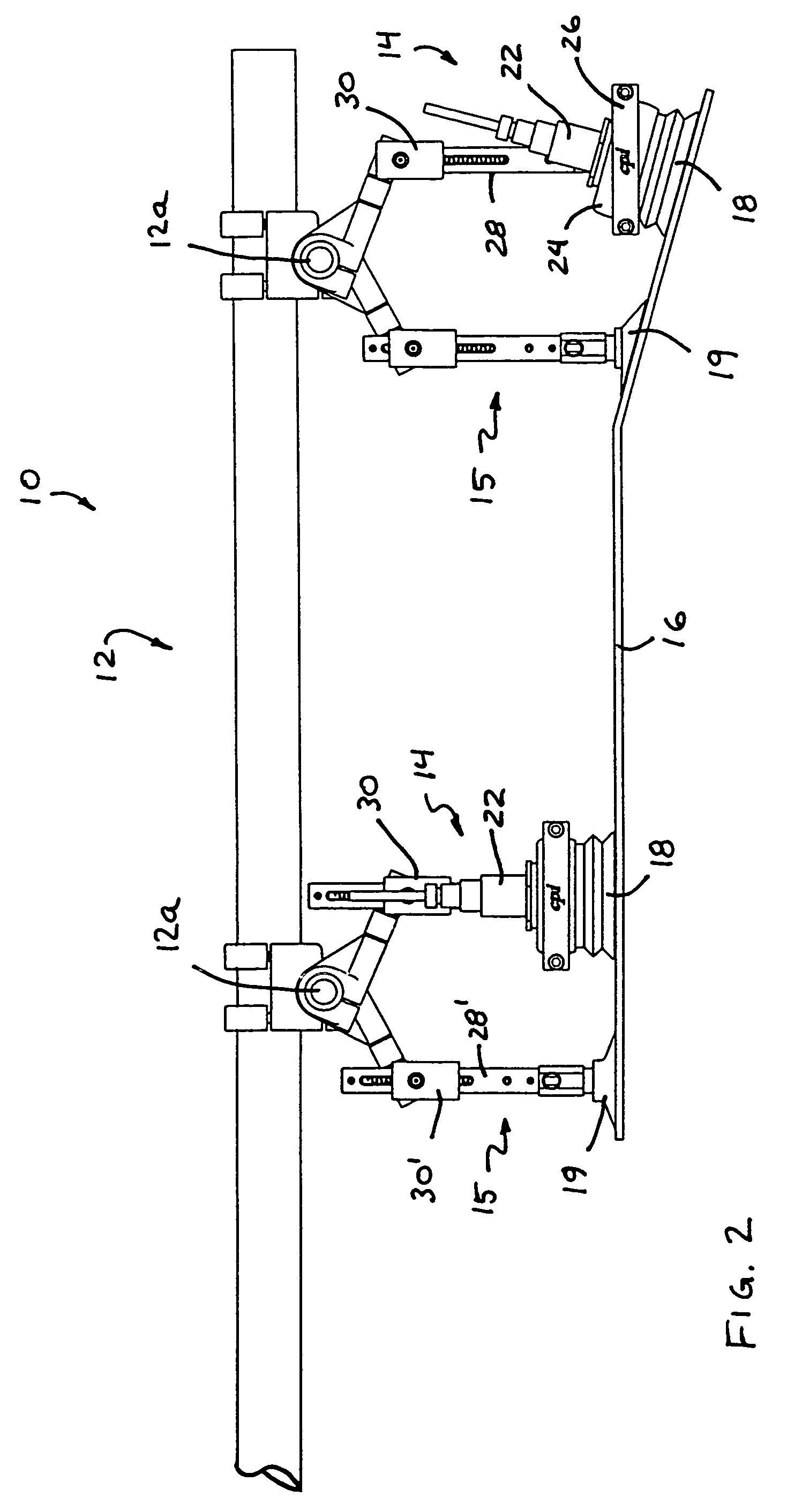
[0030]Referring now to the drawings and the illustrative embodiments depicted therein, a material handling system 10 includes a support assembly 12 that is operable to move and support a plurality of vacuum cup assemblies or material handling devices or assemblies or destackers 14, 15 (FIG. 1). Support assembly 12 is movable or adjustable or controllable to move the material handling devices 14, 15 into engagement with an object 16, where the vacuum cups 18, 19 of material handling devices 14, 15 may engage and seal to the object for picking up and moving the object 16. Material handling system 10 may include a vacuum source (not shown) for providing a vacuum at each of the vacuum cups 18 to substantially vacuum seal the vacuum cups 18 to the object 16. The material handling devices 14 provide adjustable mounts that allow the respective vacuum cups 18 to be independently pivoted and moved into engagement with an angled surface of the object via movement of the support assembly 12, a...


PUM


Abstract

A material handling device includes a vacuum cup pivotally attached to a receiving collar and pivotable to engage a surface of an object to be picked up by the material handling system. The receiving collar includes a support post and a mounting collar that is movable along the support post. The mounting collar is attachable to a support assembly that is movable to move the device toward and into engagement with the object. The mounting collar may move along the post after the respective cup engages the object and while the cups of other devices of the system are moved further toward and into engagement with the object. The material handling device may include an object sensor at a generally central region of the vacuum cup. The material handling device thus is configured to engage objects having uneven surfaces and having varying surface levels from one object to the next.

Description

FIELD OF THE INVENTION[0001]The present invention relates generally to material handling systems and, more particularly, to material handling systems that handle objects via vacuum cups or suction cups engaged with the objects and substantially sealed thereto.BACKGROUND OF THE INVENTION[0002]It is known to provide a material handling system that includes vacuum cups or the like that are adapted to be moved into engagement with an object, such as a substantially flat object or panel or the like, and to lift and move the object to a desired location. Such vacuum cups or suction cups may be moved into engagement with the object, and a vacuum source may be actuated to create a vacuum between the object and the cup such that the object is retained to the cup as it is transported to the targeted area. An example of such a vacuum cup is disclosed in U.S. Pat. No. 4,662,668, which is hereby incorporated herein by reference. The vacuum cup may include a proximity sensor that determines when ...

Claims


Application Information

Patent Timeline
Patent Type & Authority Patents(United States)
IPC IPC(8): B66C1/02B25J15/06
CPCB25J13/086B25J15/0052B25J15/0616B25J15/0061B65G47/91B25J17/0275Y10S294/907
Inventor KNISS, JASON M
Owner DELAWARE CAPITAL FORMATION INC
Why Eureka
Try Eureka