Eureka AIR delivers breakthrough ideas for toughest innovation challenges, trusted by R&D personnel around the world.

Method and device of fault location

a fault location and fault technology, applied in the direction of fault location, fault location by conductor type, instruments, etc., to achieve the effect of improving the accuracy of fault location and high accuracy

Inactive Publication Date: 2007-10-16
ABB POWER GRIDS SWITZERLAND AG
View PDF11 Cites 24 Cited by
  • Summary
  • Abstract
  • Description
  • Claims
  • Application Information

AI Technical Summary

Benefits of technology

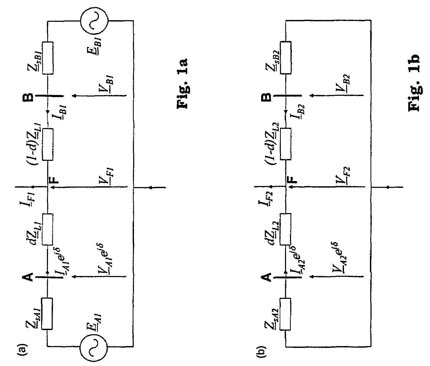
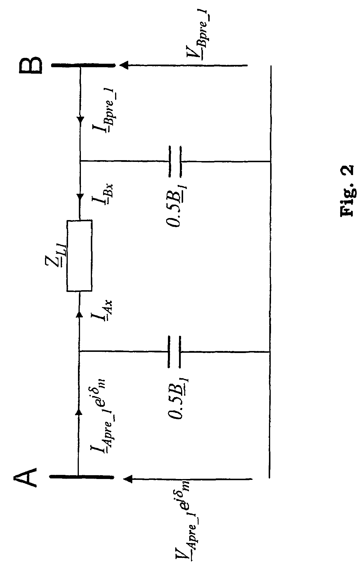
[0016]According to an optional embodiment of the invention, improved accuracy of fault location may be obtained by introducing a calculation in which the shunt capacitances of a line are compensated for. This involves iterative calculations, however limited to a simple iteration calculation, in which a total of two iterations usually provides high accuracy. The compensation of shunt capacitances is an optional refinement of the algorithm and is performed at a late stage.

Problems solved by technology

However, for some heavy fault cases (large difference of the detected instants of a fault occurrence performed at both line ends) there is a risk that the rejected solution is regarded as a correct result, while the reached solution is false.

Method used


Image

  • Method and device of fault location
  • Method and device of fault location
  • Method and device of fault location

Examples


Embodiment Construction

Characteristic of the Unsynchronized Measurements at the Line Terminals

[0029]It is considered that the measurements at the line terminals are performed without any synchronization. Thus, a fault occurrence instant is the only time relation between the measurement data from the line terminals. Physically, the actual fault occurrence instant (say, t0) is the same for both ends data. However, in real life a fault can be detected by the fault detectors (contained in protective relays or fault locators at particular line ends) in certain instants (at the substation A: tA and at the substation B: tB), which do not correspond to the actual inception instant (t0). So, taking into account that in general:

tA≠t0

tB≠t0

tA≠tB

one can expect that at both the ends the measurements from slightly shifted intervals can be frozen and used as the input data for the fault location algorithm. In some heavy cases (far end faults with high fault resistance) fault detection can be delayed even by few sampli...


PUM


Abstract

The present invention relates to a method for location of a fault utilizing unsynchronized measurements of three phase voltages and currents acquired at the line terminals without synchronization. Phasors for symmetrical components of the measured quantities are determined and used in the fault location algorithm. According to one embodiment, positive sequence phasors of post-fault quantities are used for estimation of the distance to fault and it is distinctive that such an estimation of a distance to fault is performed without essentially involving iterative techniques. In this embodiment, the fault location algorithm step is performed regardless of the fault type. In later steps, the type of fault may be obtained. According to another embodiment of the invention, at the occurrence of a fault, the type of fault is determined. If it is determined that it is not a three-phase balanced fault, negative sequence phasors are used for the estimation of the distance to fault. On the other hand, if it is a three-phase balanced fault, the incremental positive sequence phasors are used.

Description

TECHNICAL AREA[0001]The present method of fault location, which is presented here, is based on utilizing unsynchronized measurements of three phase voltages and currents acquired at the line terminals without synchronization. Phasors for symmetrical components of the measured quantities are determined and used in the fault location algorithm. Basically, positive sequence phasors of post-fault quantities are used for estimation of the distance to fault and it is distinctive that such an estimation of a distance to fault is performed without involving iterative techniques.BACKGROUND OF THE INVENTION[0002]Several methods and approaches for fault location in high voltage power systems have been developed and tried. One approach has been to use voltage / current transducers located at terminals, between which the power lines to be monitored run.[0003]One such system is disclosed in U.S. Pat. No. 5,455,776 where the transducers are connected to transducer blocks and a fault location estimat...

Claims


Application Information

Patent Timeline
Patent Type & Authority Patents(United States)
IPC IPC(8): G01R31/00G01R31/08
CPCG01R31/088G01R31/085Y02E60/728Y04S10/265Y02E60/00Y04S10/00Y04S10/22Y02E40/70
Inventor SAHA, MURAIRROSOLOWSKI, EUGENIUSZIZYKOWSKI, JAN
Owner ABB POWER GRIDS SWITZERLAND AG
Why Eureka
Eureka Blog
Learn More