Sanitary clamp

a technology for sanitary fittings and clamps, which is applied in the direction of hose connections, machine supports, other domestic objects, etc., can solve the problems of compromising the fluid tightness and pressure resistance of the connection, unable to apply an optimal amount of force, and unable to achieve optimal for

Active Publication Date: 2007-10-23
JOHNSON THEODORE DONALD +1
View PDF6 Cites 53 Cited by
  • Summary
  • Abstract
  • Description
  • Claims
  • Application Information

AI Technical Summary

Benefits of technology

[0027]The alignment of first and second distance marks on opposite ends of the cable tie provides an effective way to visually ascertain when the cable tie is properly tightened, as does the provision of a single distance mark and its alignment with a predetermined edge of the catch.

Problems solved by technology

The primary drawback of the known clamps is that they include no means for applying an optimal amount of force.
Over-tightening is particularly undesirable when a plastic fitting is used because the fitting may buckle.
Such buckling can compromise the fluid tightness and the pressure resistance of the connection.
A closely related drawback is that the force applied by the known clamps is not repeatable.
Thus, if a prior art clamp is tightened by an optimal force-providing amount, by luck, there is no means for repeating such optimal tightening the next time a clamp of the same structure is used.
However, this is a relatively expensive solution to the problem.
However, such wrenches are cumbersome and inconvenient to use.
Another drawback associated with sanitary fittings that are tightened with torque wrenches is that the installation is not tamper-evident.
Moreover, the amount of tension applied to the clamp cannot be checked by visual inspection after the torque wrench has been removed.

Method used


Image

  • Sanitary clamp
  • Sanitary clamp
  • Sanitary clamp

Examples


first embodiment

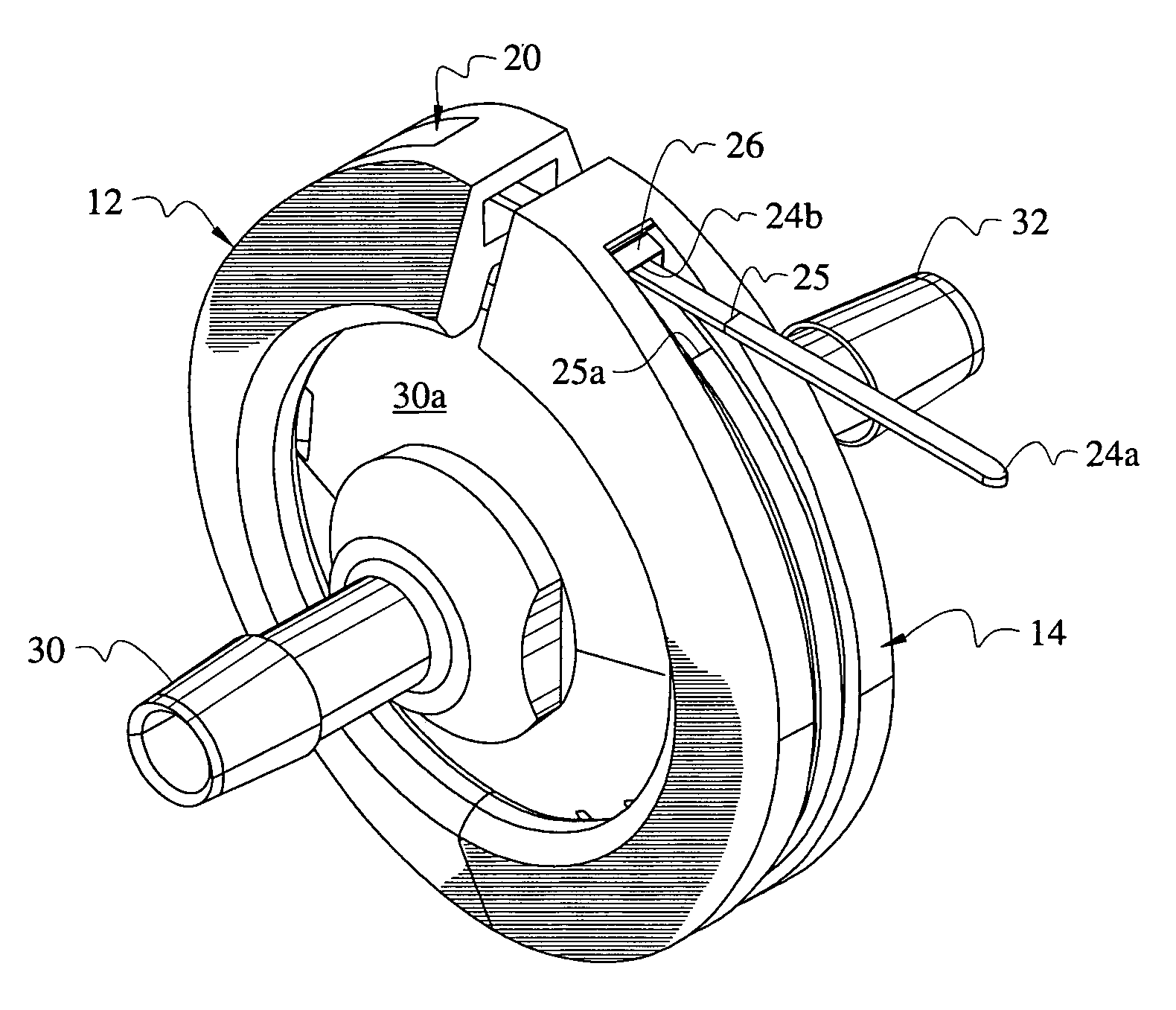
[0047]FIG. 3 depicts a first sanitary fitting 30 having flange 30a and a second sanitary fitting 32 having a similar flange, not depicted. Free end 24a of flexible cable tie 24 has been pulled through catch 26 to bring the first opposed ends of semicircular parts 12, 14 in close proximity to one another. As mentioned earlier, the tapered sidewalls of the interior channels drive the opposed flanges axially toward one another as desired as cable tie 24 is tightened. The amount of tightening required is predetermined and a first distance mark 25 is imprinted upon cable tie 24 near its distal free end 24a. In a first embodiment, a second distance mark 25a is imprinted on cable tie 24 at a predetermined location near its proximal end. A user pulls free end through catch 26 until first distance mark 25 is in registration with second distance mark 25a. The user stops pulling when said first and second distance marks are in alignment with one another so as not to over-tighten said flexible ...

third embodiment

[0056]Cable ties are typically sold in boxed quantities of twenty-five (25) and an economically-disposable, limited use, non-calibrated cable tie tensioning gun is usually included. Such an inexpensive tool, used in conjunction with the novel cable ties having distance markers, is just as effective as an expensive, commercially available, calibrated cable tie gun for bringing the tension in a cable tie to a set force as indicated on the gun. There are no cable tie guns or torque wrenches that are economically disposable. In a third embodiment, depicted in FIG. 9, a pair of “S”-shaped lobes 34, 36 are inverted with respect to one another so that they mate with one another when the clamp is closed. Lobes 34, 36 capture flexible tubing that is positioned between them in a pinching action. More specifically, each lobe engages the flexible tubing along a transverse line of contact when such tubing is disposed in sandwiched relation between said lobes. Cable tie 24 is tightened by a prede...


PUM

PropertyMeasurementUnit
flexibleaaaaaaaaaa
lengthaaaaaaaaaa
distanceaaaaaaaaaa

Abstract

A clamp for a sanitary fitting includes a first and a second semicircular part that are circumscribed by a flexible cable tie. Each semicircular part has a concave side and a convex side. A channel is formed in each concave and each convex side. The concave channels accommodate a flange of a sanitary fitting when the first and second semicircular parts are disposed in confronting relation to one another. The cable tie positioned in the convex channels circumscribes the confronting semicircular parts. A cable tie catch slidingly receives a free end of the cable tie when the cable tie circumscribes the first and second semicircular parts. A marker on the cable tie registers with the catch or another marker on the cable tie when the cable tie is under a predetermined amount of tension to ensure that the same amount of tension is consistently applied to the cable tie.

Description

CROSS REFERENCE TO RELATED APPLICATION[0001]This application claims priority to U.S. Provisional Patent Application No. 60 / 554,276 entitled: “Sanitary Clamp,” filed by the same inventors on Mar. 18, 2004.BACKGROUND OF THE INVENTION[0002]1. Field of the Invention[0003]This invention relates, generally, to clamps for sanitary fittings. More particularly, it relates to a clamp for clamping together two sanitary fittings with a force that is predetermined and which may be duplicated repeatedly.[0004]2. Description of the Prior Art[0005]Conventional sanitary clamps are typically made of stainless steel, a rigid plastic, or a combination of such materials. In a first well-known design, two semicircular parts are hingedly connected to one another at a first end and their free ends are secured to one another by a threaded stem and nut. In another well-known embodiment, the two semicircular sections are secured to one another by a flexible steel or plastic band that circumscribes them. A mec...

Claims


Application Information

Patent Timeline
Patent Type & Authority Patents(United States)
IPC IPC(8): F16L3/08
CPCF16L23/04F16L47/14F16L55/10F16L55/027Y10T24/1459Y10T24/1457
Inventor JOHNSON, THEODORE DONALDBOLEY-JOHNSON, ROBIN
Owner JOHNSON THEODORE DONALD
Why Eureka
Try Eureka