Locking element for an electrical connector

a technology of locking element and electrical connector, which is applied in the direction of coupling device connection, coupling part engagement/disengagement, incorrect coupling prevention, etc., can solve the problem that the locking element is not generally applicable, and achieve the effect of reducing the required insertion force and being convenient to inser

Inactive Publication Date: 2007-10-23
FRAMATOME CONNECTORS INT SA
View PDF19 Cites 14 Cited by
  • Summary
  • Abstract
  • Description
  • Claims
  • Application Information

AI Technical Summary

Benefits of technology

[0005]This object is achieved by providing a locking element characterized in that said insertion surface and said locking surface have an inclined orientation with respect to said longitudinal axis wherein said angle of said locking surface is larger than said angle of said insertion surface but substantially smaller than 90 degrees. Such a locking element can be easily inserted by pushing in a simple hole in the counter part that is typically present for insertion of a screw or the like. The inclination of the insertion surface is small to reduce the required insertion force. The locking element may be attached to the cable connector and locks the cable connector to the counterpart by means of the locking surface that interferes with the counterpart after the locking structure has been pushed through the hole in the counterpart. As the cable connector may need to be unlocked from the counterpart, the angle of the locking surface is substantially smaller than 90 degrees, such that the locking element can be released simply by pulling. Preferably, the insertion surface and the locking surface substantially determine the shape of the locking structure. Thus the invention provides a generally applicable locking element, that may e.g. replace a screw that is conventionally applied for locking a cable connector to a counterpart, such as a board connector or panel.

Problems solved by technology

The prior art locking approach is disadvantageous in that the locking element is not generally applicable as one or more components of the cable connector assembly have to be adapted to allow the locking element to attach the components to each other, e.g. by providing an additional groove.

Method used


Image

  • Locking element for an electrical connector
  • Locking element for an electrical connector
  • Locking element for an electrical connector

Examples


first embodiment

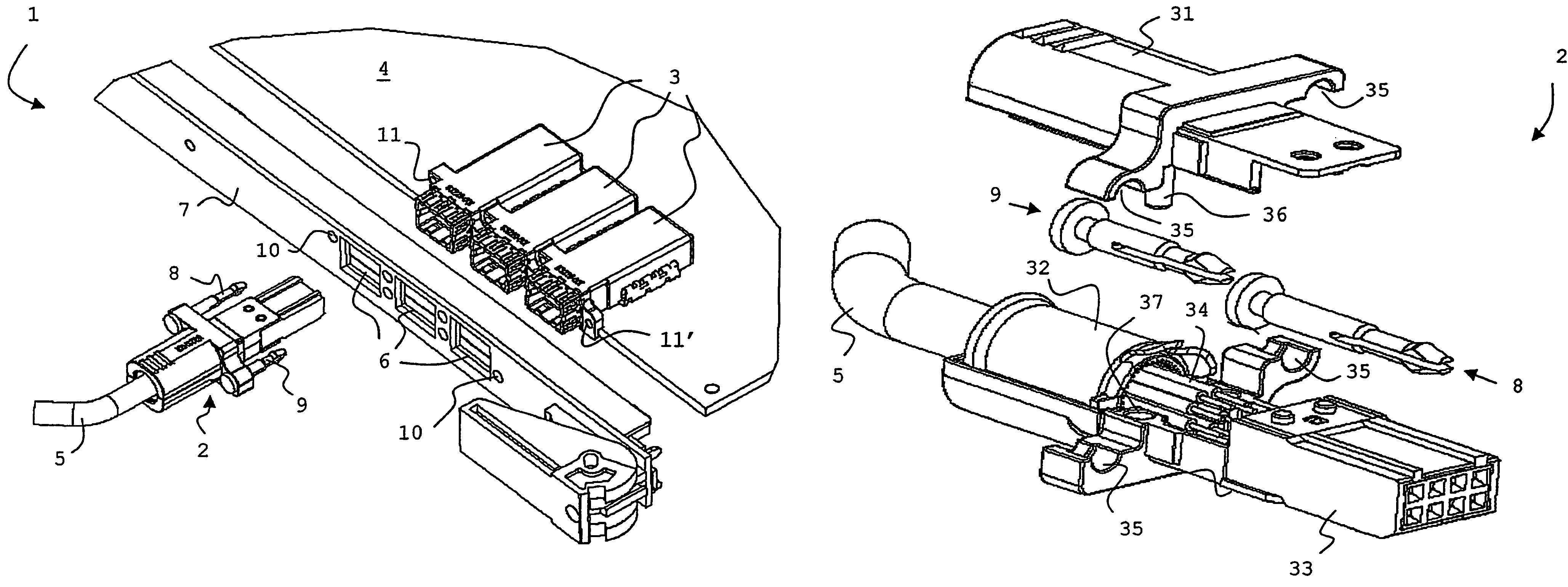
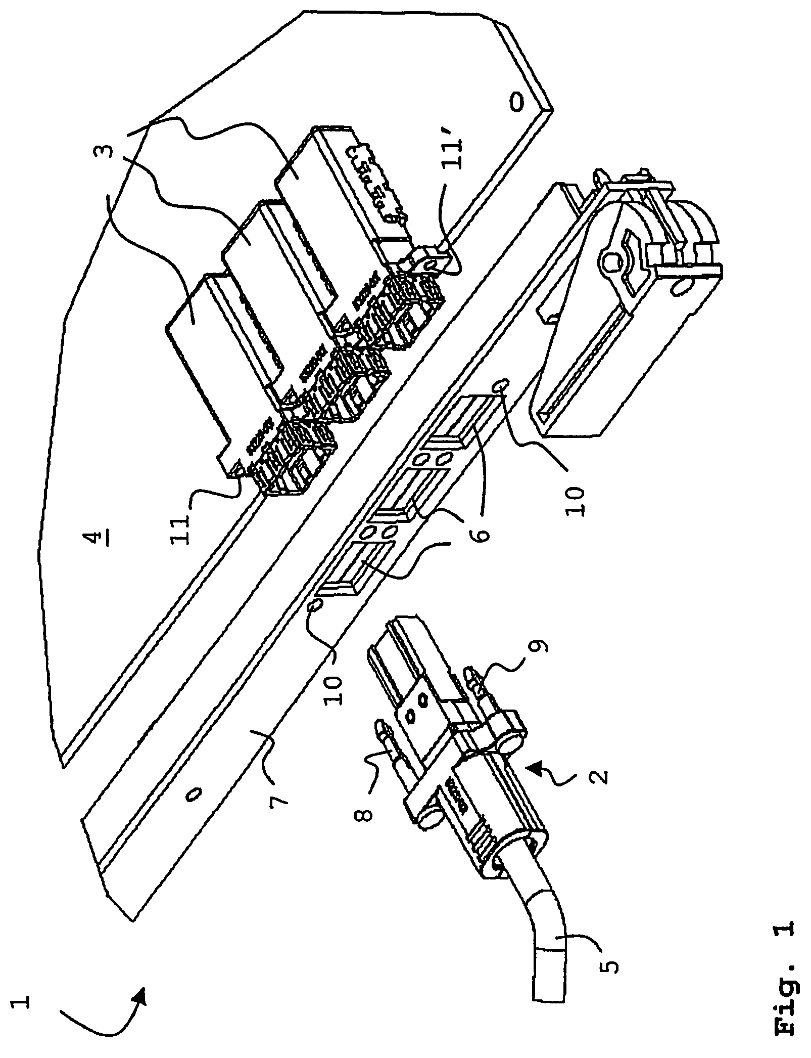
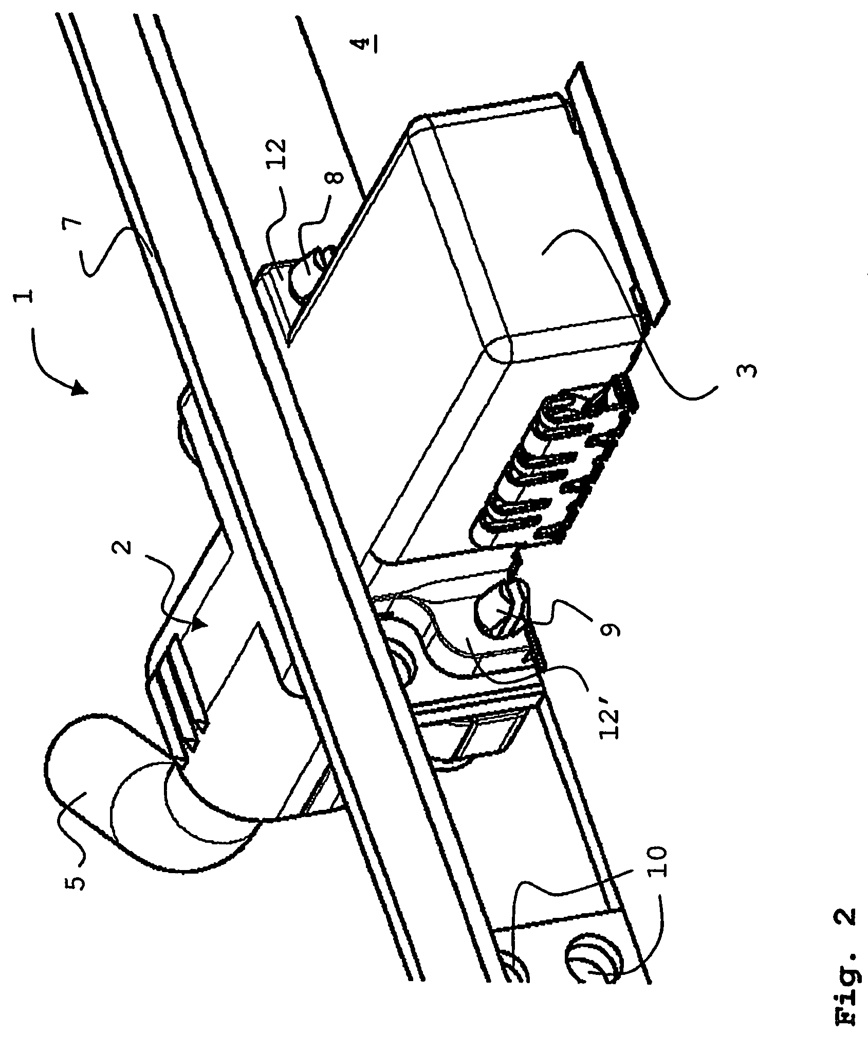
[0026]FIGS. 4A and 4B show a long pin 8 and a shorter pin 9 according to the invention and extending along a longitudinal axis 40 between a rear side 41 and a mating side 42. The short pin 9 may e.g. measure 15 mm along the longitudinal axis 40, while the long pin 8 measures 20 mm. Pins of different length are advantageous as the holes 11 and 11′ may be at different distances behind the panel 7 (see FIG. 1) such that the reference faces 12, 12′ (see FIG. 2) for locking are different for the pins 8 and 9 respectively. The pins 8, 9 comprise resilient beams 43 that extend substantially parallel to the longitudinal axis 40 and contain locking structures 44. A slit 45 is determined by the walls 46 of the beams 43. It is noted that the pins 8, 9 may contain more slits 45 such that more resilient beams 43 are provided and one or more of these beams may contain a locking structure 44. The pins 8, 9 comprise retaining structures 47, here in the form of a groove, that enable the pins 8, 9 to...

second embodiment

[0031]FIG. 7 shows a locking element 60 according to the invention extending between a rear side 61 and a mating side 62 along a longitudinal axis 63, comprising a needle eye-shaped hole 64 determining resilient beams 65, such that the beams 65 meet at the mating side 62. The beams 65 comprise a locking structure 66, comprising an insertion surface 67 and a locking surface 68 as described in more detail above. As the beams 65 are integrated at the mating side 62 to define an integrated mating end, the locking element 60 is more robust compared to the pins 8, 9 as shown in FIGS. 4A and 4B. The integrated mating end is rounded off to avoid damage in a threaded hole of a counterpart. The locking element 60 further comprises a retaining structure 69 allowing the locking element 60 to be accommodated in the spaces defined by e.g. the recesses 35 or the cable connector 2.

[0032]Instead of accommodation of the locking element 8, 9, 60 in the cable connector 2 before locking, an embodiment o...


PUM


Abstract

The invention relates to a locking element for locking and unlocking a cable connector and a counterpart, said locking element extending along a longitudinal axis between a rear side and a mating side. At the mating side two or more resilient beams extend substantially parallel to the longitudinal axis and contain one or more locking structures including an insertion surface and a locking surface building an angle with the longitudinal axis. The insertion surface and locking surface have an inclined orientation with respect to the longitudinal axis wherein the angle of the locking surface is larger than the angle of the insertion surface but substantially smaller than 90 degrees. The invention further relates to a connector system wherein one or more of these locking elements are applied to connect a cable connector and a board connector.

Description

BACKGROUND OF THE INVENTION[0001]The invention relates to a locking element for locking and unlocking a cable connector and a counterpart, said locking element extending along a longitudinal axis between a rear side and a mating side, said mating side comprising two or more resilient beams extending substantially parallel to said longitudinal axis and containing one or more locking structures comprising an insertion surface and a locking surface disposed at angles with said longitudinal axis.[0002]U.S. Pat. No. 6,511,339 discloses a cable connector assembly comprising a plug connector and a push lock retained in that plug connector by a retaining portion. The push lock comprises an annular peripheral fastener disposed on elastic beams forwardly from the retaining portion for locking to a receptacle connector. The receptacle connector comprises a groove for engaging with the fastener of the plug connector. The elastic beams can be manipulated by squeezing a press portion to connect o...

Claims


Application Information

Patent Timeline
Patent Type & Authority Patents(United States)
IPC IPC(8): H01R13/627
CPCH01R13/6278H01R13/627H01R13/434H01R13/629H01R13/62
Inventor GABRIELSSON, PER GEORGVERREYDT, BART THEO MARIA
Owner FRAMATOME CONNECTORS INT SA
Why Eureka
Try Eureka