Thin film magnetic head having toroidal coil and manufacturing method of the same

a technology manufacturing method, which is applied in the field of can solve the problems of increased coil resistance, defective, damaged first coil piece, etc., and achieve the effect of suppressing the thermal development of the thin film magnetic head, reducing the protrusion, and reducing the electric resistan

Active Publication Date: 2007-10-23
TDK CORPARATION
View PDF27 Cites 0 Cited by
  • Summary
  • Abstract
  • Description
  • Claims
  • Application Information

AI Technical Summary

Benefits of technology

[0013]Embodiments of the present invention provide a thin film magnetic head capable of further simply connecting between first coil pieces and second coil pieces with small connection resistance as well as being capable of improving the magnetization efficiency while suppressing the magnetic saturation.

Problems solved by technology

It is disclosed that the through-hole 12 is formed by etching; however, since it is difficult to form the through-holes 12 at precise positions and depths with a high degree of accuracy, there has been a problem that the connection between the first coil pieces 5 and the second coil pieces 8 becomes defective and the coil resistance is increased.
As a result, the thin film magnetic head may collide on the recording medium so as to damage the thin film magnetic head and the recording medium.
There is also a problem that the first coil pieces are damaged during forming the through-holes.
Thereby, this also produces problems of increase in electric resistance and of the thermal development.
The first coil pieces and the second coil pieces are connected together via the through-holes, so that the electric resistance and thermal development are liable to increase in the vicinity of the connection portion between the first coil pieces and the second coil pieces because of faulty connection.
Also, in the method for connecting the first coil pieces to the second coil pieces by forming through-holes, the first coil pieces may be damaged during the forming the through-holes.

Method used


Image

  • Thin film magnetic head having toroidal coil and manufacturing method of the same
  • Thin film magnetic head having toroidal coil and manufacturing method of the same
  • Thin film magnetic head having toroidal coil and manufacturing method of the same

Examples


first embodiment

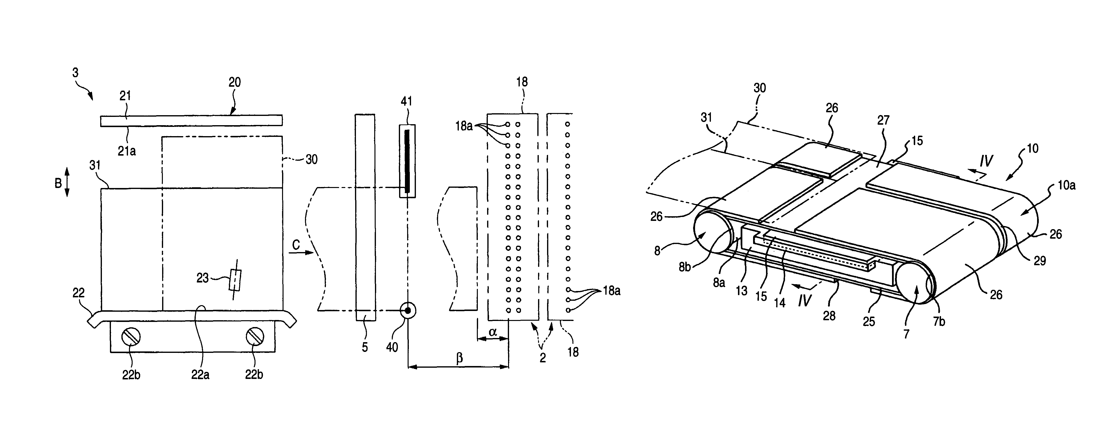
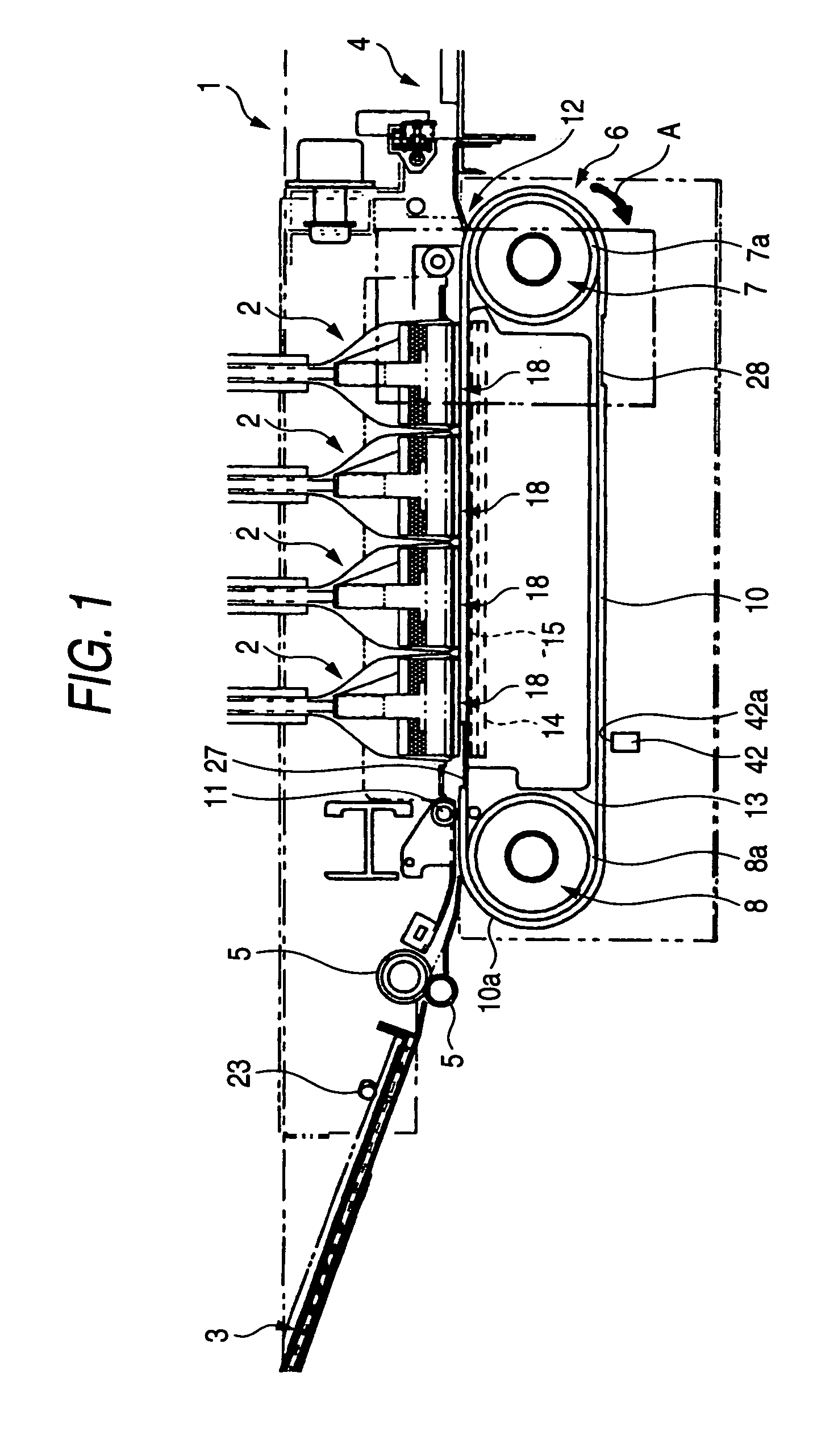
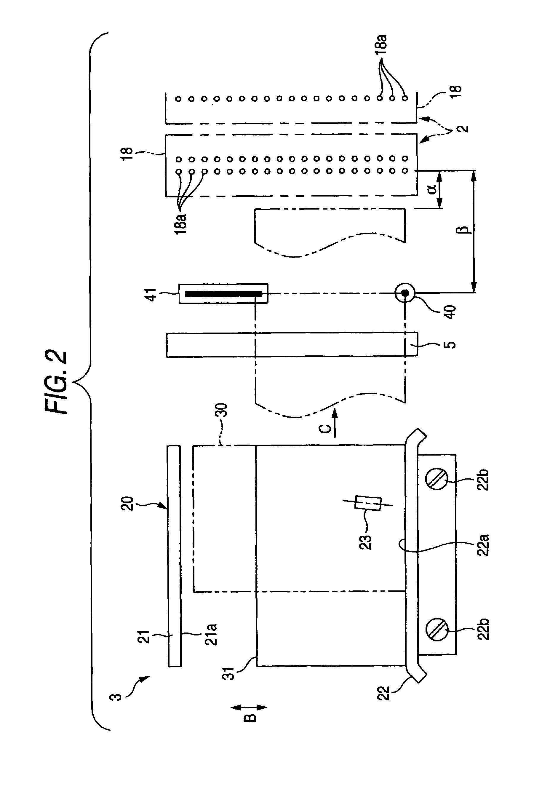
[0084]FIG. 1 is a partial sectional view of a thin film magnetic head 1A according to the present invention; FIG. 2 is a partial front view of the thin film magnetic head 1A shown in FIG. 1 showing first coil pieces, second coil pieces, which are formed mostly adjacent to an opposing surface to a recording medium, and other layers opposing the former layers in the film thickness direction by removing an upheaval layer 32, a protection layer 60, and an MR head from the drawing; FIG. 3 is a partial plan view for illustrating the coil structure of the thin film magnetic head 1A shown in FIG. 1; FIG. 4 is a partial sectional view showing the first coil pieces and a raised layer formed under the first coil pieces of the thin film magnetic head 1A shown in FIG. 1; and FIG. 5 is a partially exploded perspective view of part of the thin film magnetic head 1A shown in FIG. 1.

[0085]The X-direction in the drawings will be referred to as a track width direction, and the Y-direction as a height ...

second embodiment

[0122]FIG. 7 is a partial front view of a thin film magnetic head 1B according to the present invention and it is equivalent to FIG. 2; and FIG. 8 is a partial sectional view showing first coil pieces and raised layers formed under the first coil pieces of the thin film magnetic head 1B shown in FIG. 7 and it is equivalent to FIG. 4.

[0123]The thin film magnetic head 1B shown in FIGS. 7 and 8 has the same structure as that of the thin film magnetic head 1A shown in FIGS. 1 to 5. Therefore, in FIGS. 7 and 8, like reference characters designate like elements common to those in FIGS. 1 to 5 and the detail description is omitted.

[0124]As shown in FIGS. 7 and 8, in the thin film magnetic head 1B, the raised layer 80 is also formed on the coil insulating substrate-layer 34 formed on the lower core layer 29. The raised layer 80 is formed under the end regions 55a and 55b of the first coil pieces 55 substantially extending in the height direction from the surface opposing the recording mediu...

third embodiment

[0135]FIG. 10 is a partial front view of a thin film magnetic head 1C according to the present invention and it is equivalent to FIG. 2; and FIG. 11 is a partial sectional view showing first coil pieces and raised layers formed under the first coil pieces of the thin film magnetic head 1C shown in FIG. 10 and it is equivalent to FIG. 4.

[0136]The thin film magnetic head 1C shown in FIGS. 10 and 11 has the same structure as that of the thin film magnetic head 1A shown in FIGS. 1 to 5. Therefore, in FIGS. 10 and 11, like reference characters designate like elements common to those in FIGS. 1 to 5 and the detail description is omitted.

[0137]As shown in FIGS. 10 and 11, in the thin film magnetic head 1C, band-shaped raised layers 180, each having a predetermined width, are formed on the coil insulating substrate-layer 34 at positions spaced in the track width direction from the center B-B in the track width direction. The raised layers 180, made of an organic insulating material such as ...


PUM

PropertyMeasurementUnit
track width Twaaaaaaaaaa
heightaaaaaaaaaa
widthaaaaaaaaaa

Abstract

Within a space surrounded by a lower core layer, an upheaval layer, and a back gap layer, there are a plurality of first coil pieces arranged in a height direction and covered with a coil insulating layer. On the coil insulating layer, the upheaval layer, and a layered product formed on the back gap layer, a plurality of second coil pieces are arranged in the height direction with an insulating layer therebetween. Between the lower core layer and the first coil pieces, raised layers are formed, and the first coil pieces are in contact with the second coil pieces on connection surfaces exposed from the coil insulating layer on the raised layers.

Description

[0001]This application claims the benefit of priority to Japanese Patent Application Nos. 2003-069330 and 2003-293390, herein incorporated by reference.BACKGROUND OF THE INVENTION[0002]1. Field of the Invention[0003]The present invention relates to a thin film magnetic head having a toroidal coil structure winding about a magnetic layer, and in particular relates to a thin film magnetic head capable of further simply connecting between first coil pieces and second coil pieces with small connection resistance and capable of improving the magnetization efficiency while suppressing the magnetic saturation.[0004]2. Description of the Related Art[0005]Japanese Unexamined Patent Application Publication No. 5-250636, which will be described below, discloses a toroidal thin film magnetic head in that coil pieces are toroidally wound about a magnetic layer constituting an inductive head (recording head). The sectional shape of this thin film magnetic head is copied on FIG. 33.[0006]As shown ...

Claims


Application Information

Patent Timeline
Patent Type & Authority Patents(United States)
IPC IPC(8): G11B5/17G11B5/31
CPCG11B5/3103G11B5/17
Inventor SATO, KIYOSHI
Owner TDK CORPARATION
Why Eureka
Try Eureka