Crimp-connection sleeve tube for power transmission lines

A technology for transmission and distribution wires and crimping sleeves, which is applied in the direction of connection where permanent deformation plays a role, and can solve the problems of reducing the protective layer, small pulling force, and broken cover, and achieve the effect of improving strength

Inactive Publication Date: 2004-08-18
陈国雄
View PDF0 Cites 0 Cited by
  • Summary
  • Abstract
  • Description
  • Claims
  • Application Information

AI Technical Summary

Problems solved by technology

[0008] 1. There are only 3 types of copper clamps, the largest of which is equivalent to 60, 100, -60, 100mm 2 , for wire clips exceeding this specification, the tensile force after splicing cannot reach the standard value of 454kg; for aluminum wire clips, the tensile strength after splicing is improved by extending the length of the wire clip, but the increase in the length leads to a decrease in the number of crimping increase, making it difficult to ensure the straightness and cylindricity of the clamp after crimping, resulting in a decline in the quality of the connection
And although there are many kinds of specifications, they are all American specifications, which are not suitable for the use of Chinese metric wires. At present, there is no 8-shaped copper and aluminum crimping clamp designed for Chinese metric wires.
[0009] 2. The existing 8-shaped copper and aluminum crimping clamps with the same specifications, after crimping small-diameter to small-diameter wires, the gaps in the wire grooves cannot be effectively and tightly filled, resulting in difficulties in the tension, resistance, and temperature rise of the clamps. In line with international standards
[0010] 3. The existing 8-shaped copper and aluminum crimping clamps cannot effectively fill the gaps in the wire groove after crimping, resulting in small pulling force, high resistance, and high temperature, which may easily cause the wires in the clamp to loosen and the clamp to burn. damage, leading to power line failure accidents
[0011] 4. The existing 8-shaped copper and aluminum crimping clamps cannot effectively fill the gaps in the trenches after crimping, causing water vapor or dust to enter the gaps in the trenches, causing corrosion of the clamps and wires, and causing disconnection of the power lines ACCIDENT
[0012] 5. The existing 8-shaped copper and aluminum crimping clamps, when placed into the wire crimping, the tails of the grooves at both ends of the substrate cannot effectively fit closely along the wires and are covered in the shape of the wires, and then bent and rolled into the outer side of the interlayer in the middle of the substrate
After crimping, the grooves and wires of the clamp entity are flat, which does not meet the crimping requirements of the clamp
[0013] 6. The existing 8-shaped copper and aluminum crimping clamps, according to the above, the clamps are crimped to the entity, the wire groove and the wire are flat, the wire is easier to loosen, and the wire strands of the wire are diffused to reduce the protective layer. Easy to corrode and disconnect, resulting in power line failure accidents
[0014] 7. The existing 8-shaped copper and aluminum crimping clamps, according to the above, the crimping entity of the clamps, the bottleneck of the tension requirement standard is difficult to break through
[0021] 2. Although the H-shaped crimping clamp of the existing flat-shaped cover sheet is American standard, but the aluminum wire of the same specification is crimped to the American standard, there is also the case that the smallest pair of aluminum wire diameters are crimped, because the flat-shaped cover sheet goes deep into the The line trench cannot effectively fill the gap in the line trench, which makes it difficult to meet international standards in terms of tension, resistance, and temperature rise, and causes power line failure accidents after use
[0022] 3. In the existing H-shaped crimping clamp with a flat cover, when crimping the largest pair of aluminum wires with the same specification, the flat cover is just covered and connected to both ends of the H-shaped crimp body, forming two fragile Thin seams are more likely to corrode and fall off
[0023] 4. When the H-shaped crimping clamp of the existing flat cover piece often needs to be crimped more than once, the cover piece often breaks from the first crimping point, which seriously affects the crimping and connection quality of the aluminum wire
[0024] 5. For the H-shaped crimping clamp of the existing flat-shaped cover, when the wire is crimped, the cover needs to be folded up at 45 degrees in order to insert the wire, and it is often folded up at 90 degrees, which will easily cause the cover to break, because the flat-shaped The cover sheet does not have an inner stop groove design. After the wire is folded up and placed into the wire groove and folded down to the bottom to prevent the wire from slipping out of the wire groove, it is easy to break and fall off, so that it cannot be crimped.
[0025] 6. The situation in item 5 above is most likely to occur during live work, because the operator wears rubber gloves plus protective leather gloves, and his fingers are very inflexible, and the flat cover is often broken, resulting in time-consuming construction, especially often Occurs in unskilled workers

Method used


Image

  • Crimp-connection sleeve tube for power transmission lines
  • Crimp-connection sleeve tube for power transmission lines
  • Crimp-connection sleeve tube for power transmission lines

Examples


Embodiment 1

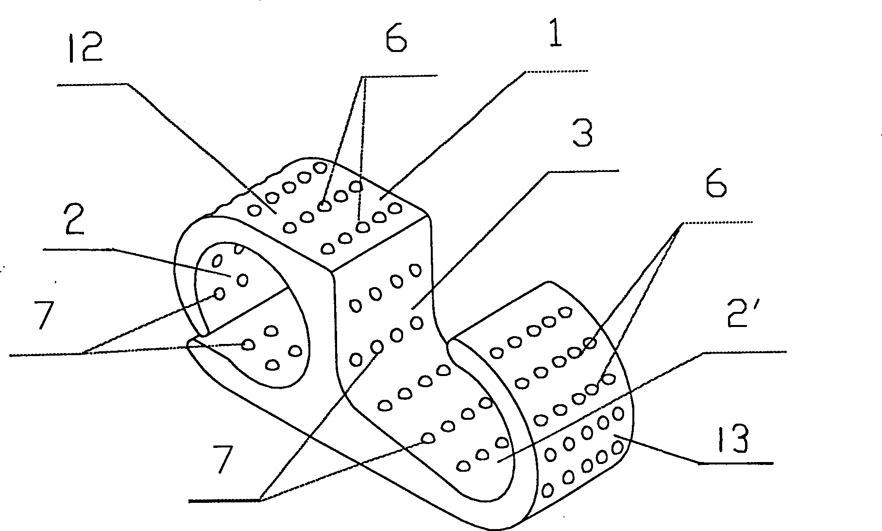
[0111] Embodiment one, such as figure 1 As shown, a crimping sleeve for transmission and distribution wires according to the present invention, the sleeve is a columnar base 1 with a cross-section of an 8-shaped opening, and two wire grooves 2 that are in contact with the wires are provided at both ends of the base 1 , 2', a partition 3 separating the two ends of the trench is provided between the two trenches, the one trench 2 is surrounded by a wire hook 12 that is approximately open and circular and the compartment 3, and the other The line groove 2' is surrounded by a round hook-shaped line hook 13 that is greater than, equal to, or less than a semicircle and an interlayer 3, forming a base body 1 that is a columnar body with a cross-section in the shape of an 8-shaped reverse opening. The o" part is two line grooves 2, 2', which are in the shape of through holes. On the inner surface of the two line grooves 2, 2' and the surface of the middle spacer layer 3, there are lo...

Embodiment 2

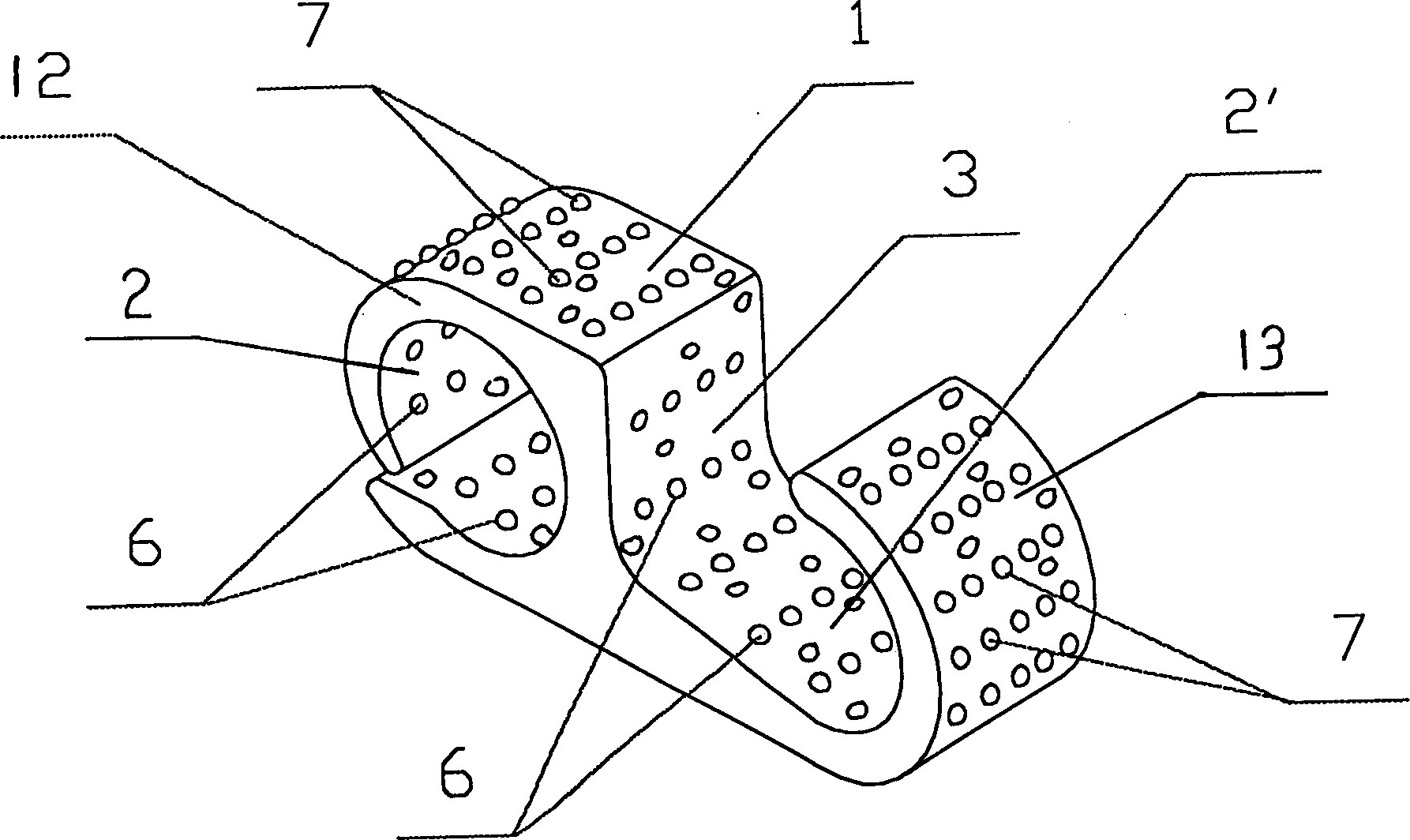
[0113] Embodiment two, such as figure 2 As shown, the difference between this embodiment and the previous embodiment is that the locking protrusions 7 are arranged on the outer surfaces of the wire grooves 2, 2', and the locking recesses 6 are arranged on the inner surfaces of the wire grooves 2, 2'. . At the beginning of crimping, the recesses on the inner surface will be closed early, which is beneficial to improve the compressive stress on the inner surface of the groove and contribute to the bending of the groove; the locking protrusion on the outer surface improves the strength and helps the end of the groove to stick The combined wire is beneficial to crimping and sealing with the wire, which can make the wire groove effectively cover the wire in the shape of wire diameter, and the wire clip is approximately cylindrical. When the locking protrusions and locking recesses are distributed in a point shape, the recesses and protrusions have the same effect.

Embodiment 3

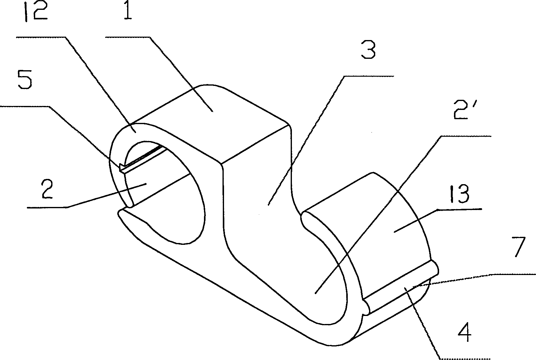
[0114] Embodiment three, such as Figure 3A , 3B , 3C, 3D, 3E, and 3F, a crimping sleeve for power transmission and distribution lines according to the present invention, the sleeve is a columnar base 1 with an open cross-section, and two ends of the base 1 are provided with The two wire grooves 2, 2' that the wires contact are provided with an interlayer 3 separating the wire grooves at both ends between the two wire grooves. The wire groove 2 is composed of a wire hook 12 that is approximately open and circular and a spacer. Surrounded by layer 3, the other line groove 2' is surrounded by a round hook 13 that is larger than, equal to or smaller than a semicircle and an interlayer 3, forming a base 1 that is a column with a cross-section in the shape of an 8-shaped reverse opening Body, the "o" part of the 8 character is two line grooves 2, 2', which are in the shape of through holes; it also includes a locking groove 5 and a locking rod 4.

[0115] Such as Figure 3A As s...


PUM


Abstract

A sleeve tube or line clamp for crimp connection of power transmission lines has a pile-shaped main body with cross section of open 8 shape or H shape, and two line channels at both ends. Both line channels are isolated from each other by partition. On the surface of main body, there are cancave and / or convex locking dots or locking slots and / or ridges. Its advantages are tight connection, great pull force, and low contact resistance and temp raising.

Description

technical field [0001] The invention relates to a crimping sleeve mainly used for high-voltage and low-voltage transmission and distribution lines, commonly known as a wire clip, especially a copper, aluminum or other metal material that can crimp the wire clip and the wire into one. Shaped, H-shaped clamps. Background technique [0002] Crimping sleeves, commonly known as wire clamps, are commonly used electrical fittings. They are divided into two types: "tension type wire clamps" and "non-tension type wire clamps". "Non-tension type wire clamps" are further divided into "bolt locking type". There are two types of "crimping type", and the crimping type is divided into two types: open 8 shape and H shape. [0003] At present, the "bolt locking type" "parallel groove clamp" is widely used in China. This kind of clamp is made of two grooves and two or more bolt holes on a thick aluminum plate, and then two Or two or more double-groove aluminum sheets and the pressure of the...

Claims


Application Information

Patent Timeline
Patent Type & Authority Patents(China)
IPC IPC(8): H01R4/18
Inventor 陈国雄
Owner 陈国雄
Why Eureka
Try Eureka