Method and apparatus for aiding image interpretation and computer-readable recording medium storing program therefor

a technology of image interpretation and recording medium, which is applied in the field of method and apparatus for aiding image interpretation and to a computer-readable recording medium storing a program therefor, can solve the problems of difficult direct comparison of a maximal inhalation image and a maximal exhalation image, and the inability to carry out high-quality alignmen

Inactive Publication Date: 2007-10-23
FUJIFILM HLDG CORP +1
View PDF10 Cites 25 Cited by
  • Summary
  • Abstract
  • Description
  • Claims
  • Application Information

AI Technical Summary

Benefits of technology

[0013]The present invention has been conceived based on consideration of the above circumstances. An object of the present invention is therefore to provide a method and an apparatus for aiding efficient comparative image reading through alignment of a subject in two images that are not adjacent to each other in three or more images arranged in temporal order representing a change in a state of the subject, and to provide a computer-readable recording medium storing a program therefor.

Problems solved by technology

Therefore, a density change in lung fields is only indirectly and ineffectively understood between a maximal inhalation image and a maximal exhalation image.
Therefore, direct comparison of a maximal inhalation image and a maximal exhalation image is difficult.
However, since the images have too much a difference as has been described above, alignment cannot be carried out with high accuracy.
Consequently, in the case where comparative image reading is carried out between two images that are not adjacent to each other in three or more images arranged in temporal order for representing changes in a subject, observation of a necessary one of the changes alone has been impossible through the comparative image reading even if an effect of the other change or changes is removed after alignment of the subject in the two images.

Method used


Image

  • Method and apparatus for aiding image interpretation and computer-readable recording medium storing program therefor
  • Method and apparatus for aiding image interpretation and computer-readable recording medium storing program therefor
  • Method and apparatus for aiding image interpretation and computer-readable recording medium storing program therefor

Examples


first embodiment

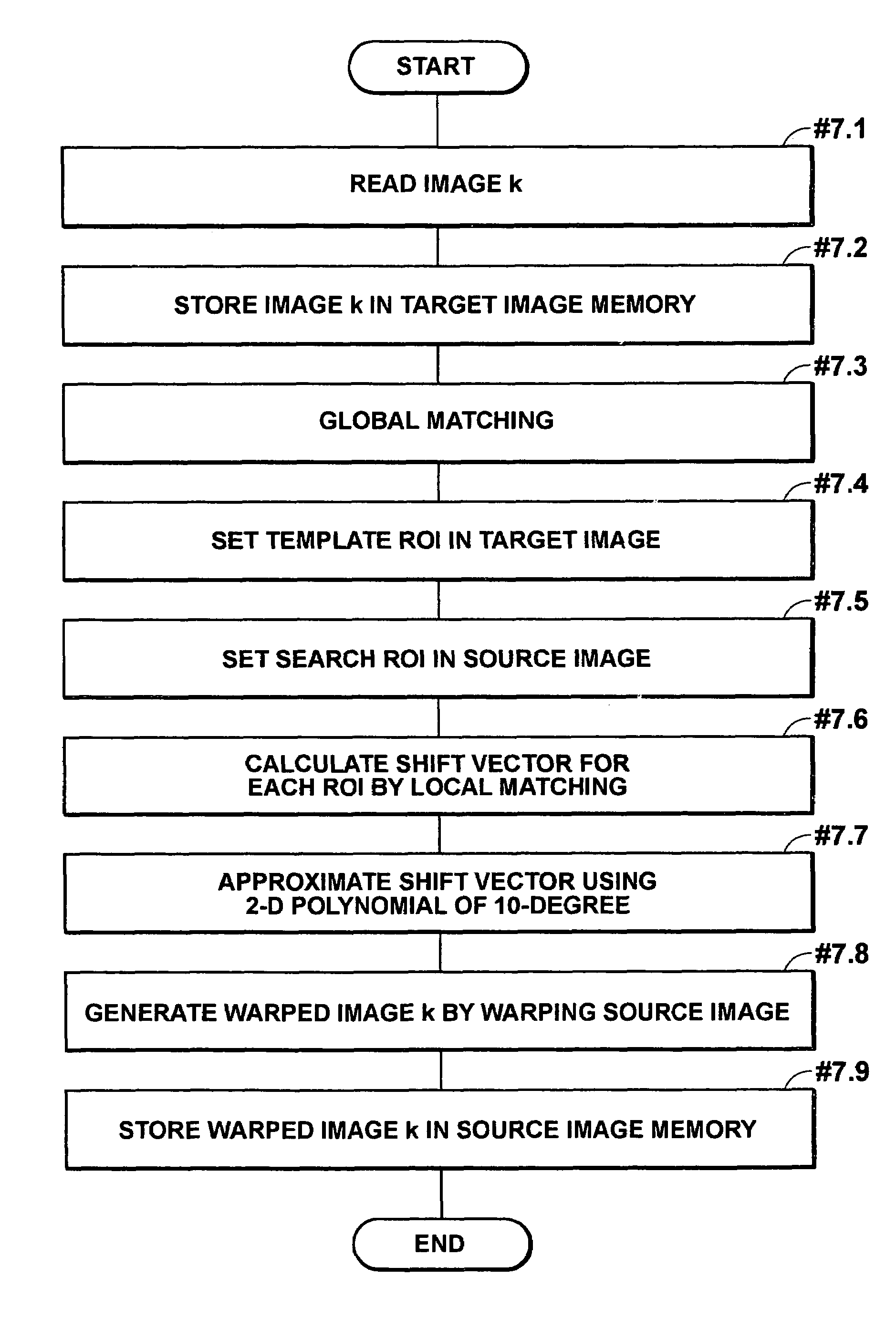
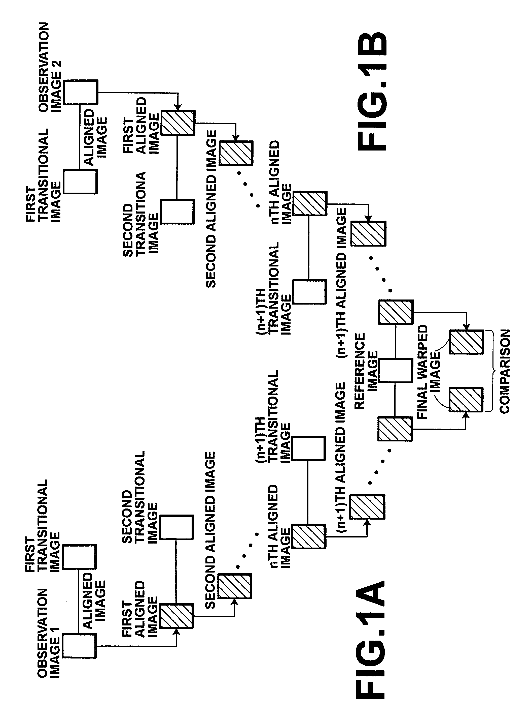
[0117]An image interpretation aiding apparatus A of the present invention has a function of generating two final warped images by aligning the subject in the maximal inhalation image and the maximal exhalation image to the subject in a predetermined reference image. A diagnostician interprets the two final warped images through comparative image reading thereof.

[0118]FIG. 5 is a block diagram showing the configuration of the image interpretation aiding apparatus A and a peripheral system and flows of data. As shown in FIG. 5, the image interpretation aiding apparatus A comprises cumulative warped image generation means 1. The cumulative warped image generation means 1 reads files of images 1 to N (where N represents the number of the images) stored in image storage means 4, according to reading condition information specified by the diagnostician with use of reading condition specification means 2. The cumulative warped image generation means 1 then generates the two final warped im...

second embodiment

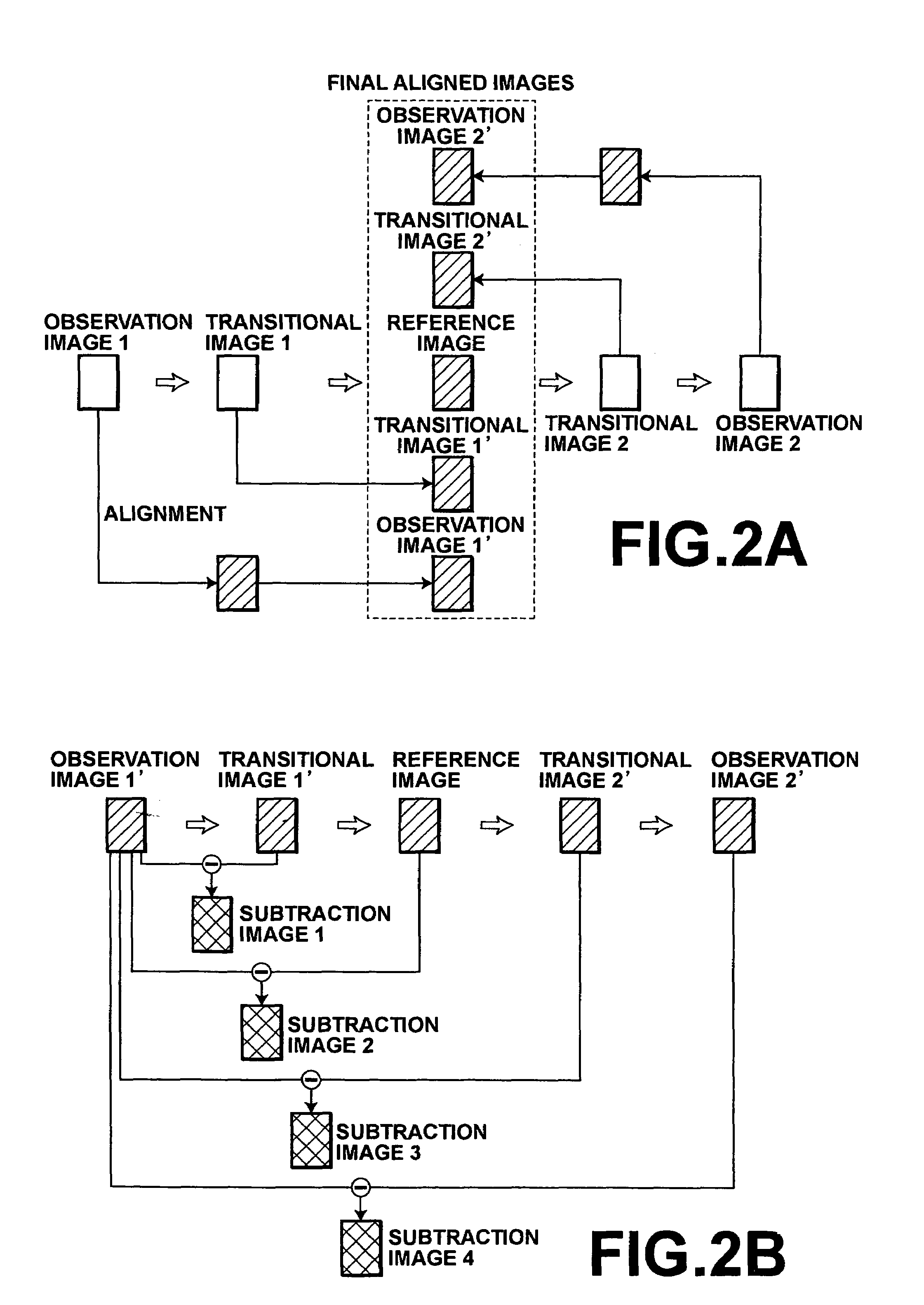
[0158]An image interpretation aiding apparatus B of the present invention has a function of generating a subtraction image between the two final warped images generated by aligning the subject in the maximal inhalation image and the maximal exhalation image to the subject in the predetermined reference image.

[0159]FIG. 12 is a block diagram showing the configuration of the image interpretation aiding apparatus B and a peripheral system and flows of data. The only difference between the image interpretation aiding apparatus B and the image interpretation aiding apparatus A is that the image interpretation aiding apparatus B has final subtraction image generation means 5 for generating the subtraction image. Hereinafter, this difference will be mainly described.

[0160]The final subtraction image generation means 5 comprises a main storage for storing a program executable by the image storage server 11 and data and instructions used by the CPU or the program of the image processing serv...

third embodiment

[0165]An image interpretation aiding apparatus C of the present invention has a function of generating a map image enabling recognition of segments in the final subtraction image by classifying pixel values in the final subtraction image into the segments according to one or more threshold values.

[0166]FIG. 14 is a block diagram showing the configuration of the image interpretation aiding apparatus C and a peripheral system, and flows of data. The only difference between the image interpretation aiding apparatus C and the image interpretation aiding apparatus B is that the image interpretation aiding apparatus C has map image generation means 6 for generating a final map image by carrying out thresholding or the like on the final subtraction image. Hereinafter, this difference will be described mainly.

[0167]The map image generation means 6 comprises a main storage for storing a program executable by the image storage server 11 and data and instructions used by the CPU or the program...


PUM


Abstract

The same subject can be accurately aligned for effective interpretation of two observation images representing a change in the subject and not adjacent to each other in three or more images arranged in temporal order of the change. The subject in one of the observation images is aligned to the subject in a transitional image adjacent to the observation image, and an aligned image is generated. The same procedure is repeated between the previous aligned image and a transitional image adjacent to the previous transitional image to generate another aligned image. A final aligned image is generated by aligning the subject in the observation image to the subject in a reference image. This procedure is carried out for the other observation image and a final aligned image is also generated by alignment to the reference image. A diagnostician compares the two final aligned images.

Description

BACKGROUND OF THE INVENTION[0001]1. Field of the Invention[0002]The present invention relates to a method and an apparatus for aiding image interpretation and to a computer-readable recording medium storing a program therefor. More specifically, the present invention relates to a method and an apparatus for aiding comparative reading of two images that are not adjacent to each other among three or more images arranged in temporal order for representing a change in the state of a subject, and to a computer-readable recording medium storing a program therefor.[0003]2. Description of the Related Art[0004]Comparison and observation of only type of change, based on a plurality of images obtained by photography of a subject showing simultaneous changes of two or more types, is necessary in some cases. In this case, by removing an effect of the change or changes of the other type or types that are not a target of observation, the change of the type as the observation target can efficiently...

Claims


Application Information

Patent Timeline
Patent Type & Authority Patents(United States)
IPC IPC(8): G06K9/00A61B6/00G06K9/68G06T1/00G06T7/00G06T7/60H04N5/325
CPCG06T7/0012G06T7/0024G06T2207/30061G06T7/30
Inventor OOSAWA, AKIRA
Owner FUJIFILM HLDG CORP
Why Eureka
Try Eureka