Fluid dispenser member and a dispenser including such a member

a technology of a dispenser and a member, which is applied in the direction of liquid transferring devices, instruments, single-unit apparatuses, etc., can solve the problem of differential cylinder sliding in a leaktight manner inside the differential cylinder

Inactive Publication Date: 2007-10-30
APTAR FRANCE SAS
View PDF15 Cites 15 Cited by
  • Summary
  • Abstract
  • Description
  • Claims
  • Application Information

AI Technical Summary

Benefits of technology

[0008]To do this, the present invention provides a fluid dispenser member designed to be associated with a fluid reservoir having a neck, said member comprising: a body defining at least part of a fluid chamber, said body being provided with fixing means for fixing onto the neck of the reservoir, said body including a fluid inlet connecting the inside of the reservoir to the fluid chamber; a pusher mounted on the body in such a manner as to be axially displaceable between a rest position and a driven-in position; and a spring urging the pusher into the rest position, wherein the spring is housed entirely inside the pusher, and the body is made of a transparent or translucent material. Thus, compared with a conventional prior-art stopper, the pusher has the visual appearance of a stopper member, while the body has the visual appearance of a base portion fixed onto the reservoir or flask. By housing the spring entirely inside the pusher, the spring is not visible to the user. In addition, by making the body of transparent or translucent plastics material, said body comes closer to the visual appearance of the conventional base portion of a conventional stopper. The spring is the component of the dispenser member that can be seen most easily, given that it is conventionally made of steel. This is why it is important, in the context of the present invention, to mask it inside the pusher, which may itself be made of an opaque, white, or colored plastics material.
[0013]According to another characteristic, the piston element forms a movable inlet-valve member that is designed to be pressed in leaktight manner against an inlet valve seat formed on the body. In an embodiment, the piston element is housed entirely inside the pusher. It is thus possible to omit using a steel ball as a movable inlet-valve member. Said steel ball might be visible through the transparent or translucent body, thereby spoiling the appearance of the dispenser member, and as a result, the appearance of the dispenser as a whole.
[0017]According to another characteristic of the invention, the reservoir, the body, and the pusher have an identical maximum outside diameter, such that the dispenser has an overall cylindrical appearance that is advantageously circular. This tubular aspect is further reinforced when the fixing means for fixing the body are disposed around the reservoir neck, and when the pusher extends around the body.

Problems solved by technology

When the pusher is pressed, the main piston rises in the main cylinder of the pusher, thereby causing the differential piston to slide in leaktight manner inside the differential cylinder.

Method used


Image

  • Fluid dispenser member and a dispenser including such a member
  • Fluid dispenser member and a dispenser including such a member
  • Fluid dispenser member and a dispenser including such a member

Examples


second embodiment

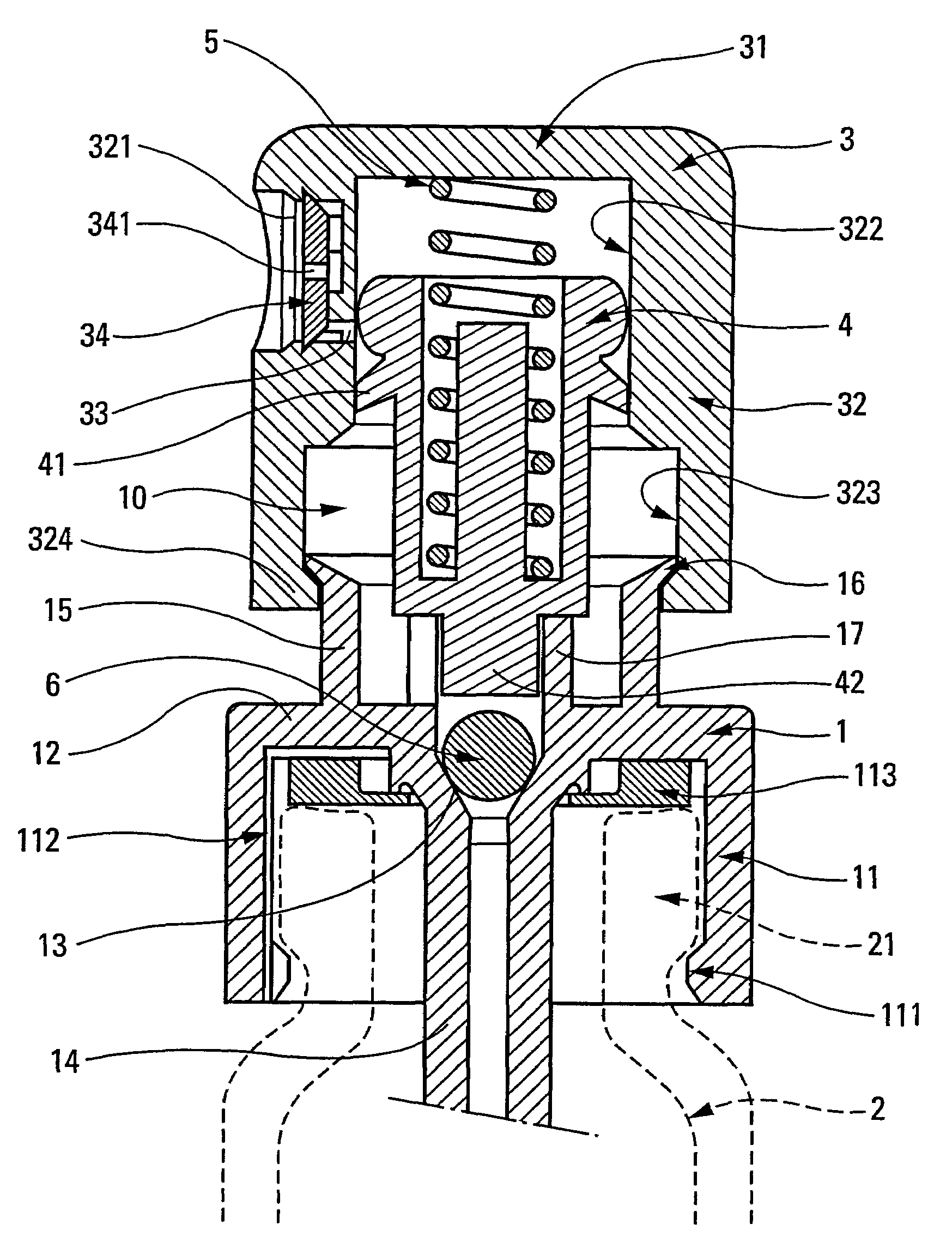
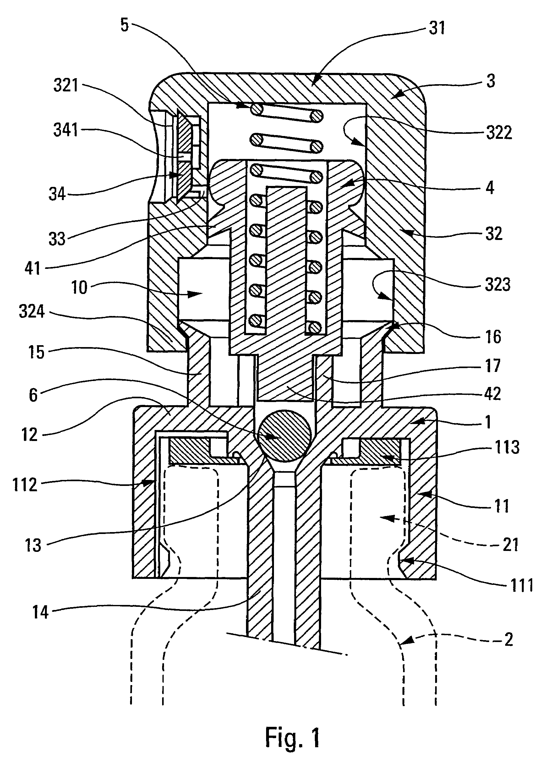
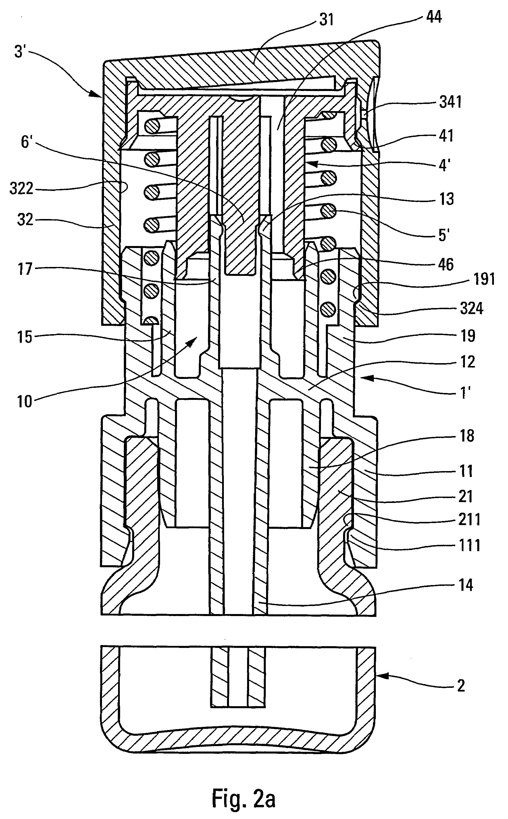
[0025]In the two embodiments in the figures, the dispenser member is a pump of the precompression type. More particularly, the pump is of the “pusher-pump” type in the meaning defined above. However, the present invention can apply to other types of pump which are not pusher-pumps. However, in the two embodiments shown in the figures, the dispenser member or pump comprises the following component elements, namely: a pump body 1, a pusher 3, a piston element 4, and a spring 5. For the second embodiment in FIGS. 2a and 2b, the numerical references are given prime symbols.

[0026]The body 1, 1′ is preferably made of injection-molded plastics material. In the invention, the plastics material used is transparent or at least translucent so that it is possible to see through the body.

[0027]The body 1, 1′ is provided with fixing means 11, which, in this case, are advantageously made integrally as a single piece with the body. The fixing means 11 comprise an outer peripheral skirt designed to ...

first embodiment

[0032]In the first embodiment in FIG. 1, the body 1 also forms a ring 15 which extends upwards from the plate 12. At its top free end, the ring 15 defines a lip 16 for the main piston. In addition, the body 1 defines an inlet duct 17 which is crenellated in part, and which extends from the plate 12 just in the extension of the seat 13.

[0033]In the second embodiment in FIGS. 2a and 2b, the body 1′ forms a ring 15 which extends upwards from the plate 12. The inside cylindrical wall of the ring 15 serves as a main cylinder in which a main piston 46 slides (as described below). In addition, the body 1′ forms an inner guide bushing 19 which is provided with an abutment profile 191 which extends over the outer periphery of the bushing 19. The inlet duct 17 extends in concentric manner inside the ring 15, which itself extends in concentric manner inside the guide bushing 19.

[0034]In the embodiments described above, the body 1 and 1′ is advantageously made integrally as a single piece with ...


PUM


Abstract

A fluid dispenser member designed to be associated with a fluid reservoir having a neck, said member comprising: a body defining at least part of a fluid chamber, said body being provided with fixing means for fixing onto the neck of the reservoir, said body including a fluid inlet connecting the inside of the reservoir to the fluid chamber; a pusher mounted on the body in such a manner as to be displaced axially between a rest position and a driven-in position; and a spring urging the pusher into the rest position, wherein the spring is housed entirely inside the pusher, and the body is made of a transparent or translucent material.

Description

[0001]The present invention relates to a fluid dispenser member that is generally designed to be associated with a fluid reservoir in order to constitute together a fluid dispenser. The dispenser member is generally actuated manually by means of one of the user's fingers. The fluid is dispensed in the form of a jet of finely-sprayed droplets, in the form of a continuous stream, or even in the form of a bead of fluid, particularly in the case of viscous fluids such as cosmetic creams. Such a fluid dispenser member can be used in the fields of perfumery, cosmetics, or even pharmacy, in order to dispense fluids of various degrees of viscosity.BACKGROUND OF THE INVENTION[0002]The present invention relates more particularly, but not exclusively, to a type of dispenser member which is commonly designated under the term “pusher-pump”. Such a designation is explained by the fact that the dispenser member includes a pusher forming not only a dispenser orifice, but also defining a portion of ...

Claims


Application Information

Patent Timeline
Patent Type & Authority Patents(United States)
IPC IPC(8): B65D88/54G01F11/00B05B1/34B05B11/00
CPCB05B1/3436B05B1/3457B05B11/3004B05B11/3094B05B11/3074B05B11/3077B05B11/304B05B11/3022B05B11/307B05B11/1004B05B11/1022B05B11/104B05B11/107B05B11/1047B05B11/1077B05B11/1094B05B11/1074
Inventor GARCIA, FIRMIN
Owner APTAR FRANCE SAS
Why Eureka
Try Eureka