
Fire-blocking door lock structure

a door lock and fire-blocking technology, applied in the direction of door/window fittings, mechanical devices, carpet fasteners, etc., can solve the problems of easy damage to the lock inability to easily restore to the original position, and damage to the door latch. , to achieve the effect of prolonging the lifespan of the door latch, good lock-up condition, and easy opening

Active Publication Date: 2007-10-30
LIN CHING TIEN
View PDF19 Cites 29 Cited by
  • Summary
  • Abstract
  • Description
  • Claims
  • Application Information

AI Technical Summary

Benefits of technology

[0013]In view of said prior technique of a conventional fire-blocking door lock, the primary objective of the present invention is to provide a fire-blocking door structure enabling a fire-blocking door to be securely latched with a good condition when the fire-blocking door is closed.
[0014]Another objective of the present invention is to provide a fire-blocking door lock, which enables a door lock to be easily unlatched by a press force.
[0016]Another objective of the present invention is to provide a fire-blocking door lock structure, which has a longer lifespan for door latch usage.
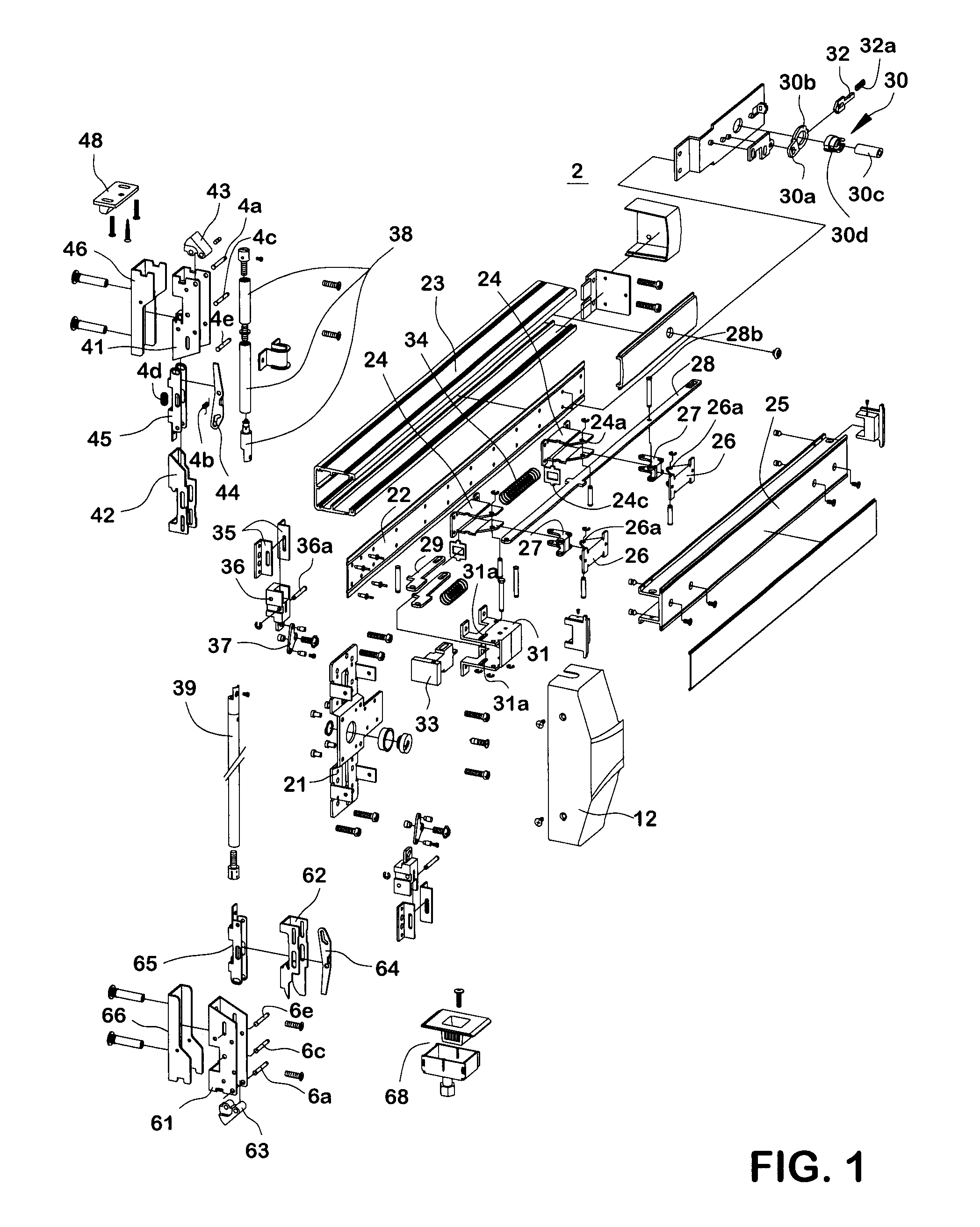
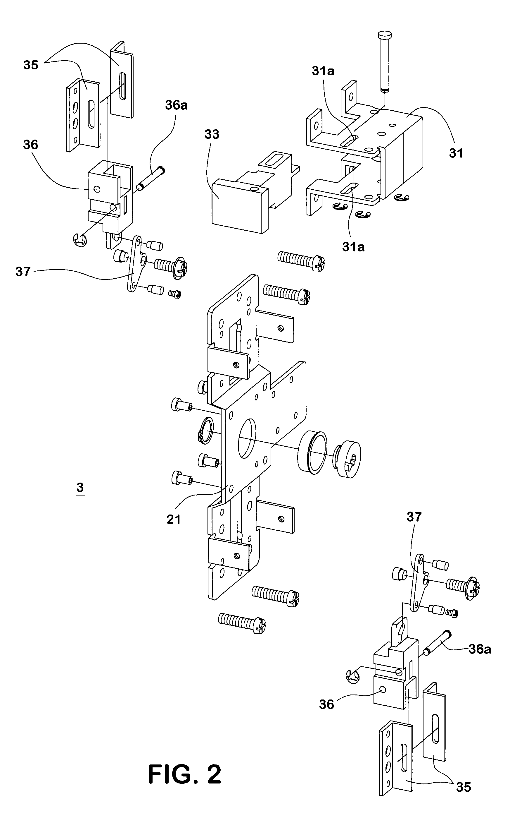
[0018]The middle latch mechanism comprises a slide support, a latch block pivotally and shiftably installed inside the slide support, two driving pieces smoothly shifted and separately joined to the slide support and the latch block, and two pairs of sliding blocks that are driven by the driving pieces by dint of pins piercing through the driving pieces. The slide support is roughly mounted on the center of the base body inside the casing. The driving pieces are pivotally positioned in the center of the base body and rotated smoothly. The latch block is connected to the slide support and pierced through by a pin to a hole at the front end of the slide support. The recess portion of the latch block enables the latch block not to be contacted with the casing while the latch block is retracted inside and extended outside the slide support. The sliding blocks are movably, pivotally installed inside the sliding block supports in the opposite directions on both lateral sides of the base body and pivotally joined to the driving pieces.
[0023]Consequently, the fire-blocking door lock structure of the present invention can enable a fire-blocking door lock to be securely latched and kept in a good lock-up condition when the fire-blocking door is closed. The present invention, therefore, can truly improve various drawbacks of a conventional fire-blocking door lock structure, enabling a user to easily use the fire-blocking door lock of the present invention, enabling the door to be easily opened by a press force, enabling the components and parts to be modularized and enabling the lifespan of the door latch to be prolonged; thereby maintaining the secured efficacy of using the fire-blocking door lock.

Problems solved by technology

Moreover, excessive force on the latch body 12d could cause damage to the door latch.
Moreover, as there is no an appropriate restorable force provided by any structure or components among the first latch body 12g, the second latch body 12h and the bar link 12f, therefore, when the opened door is locked up, the first latch body 12g and the second latch body 12h can not be easily restored to the original positions; or the lock of the door latch is easily damaged owing to an external force or improper beats or strikes.
Said damages to the door latch not only easily shorten the lifespan of the door latch, but also result in the problem of failing to latch or unlatch the door lock.
The said conventional fire-blocking door lock structure has various problems; for example, the door lock structure requires a greater physical strength to actuate the door latch, and in addition, the lifespan of the door latch is easily shortened and the efficacy of a fire-blocking door usage is reduced without any proper support, actuating mechanisms and restorable force by various door lock components.

Method used


Image

  • Fire-blocking door lock structure
  • Fire-blocking door lock structure
  • Fire-blocking door lock structure

Examples


Embodiment Construction

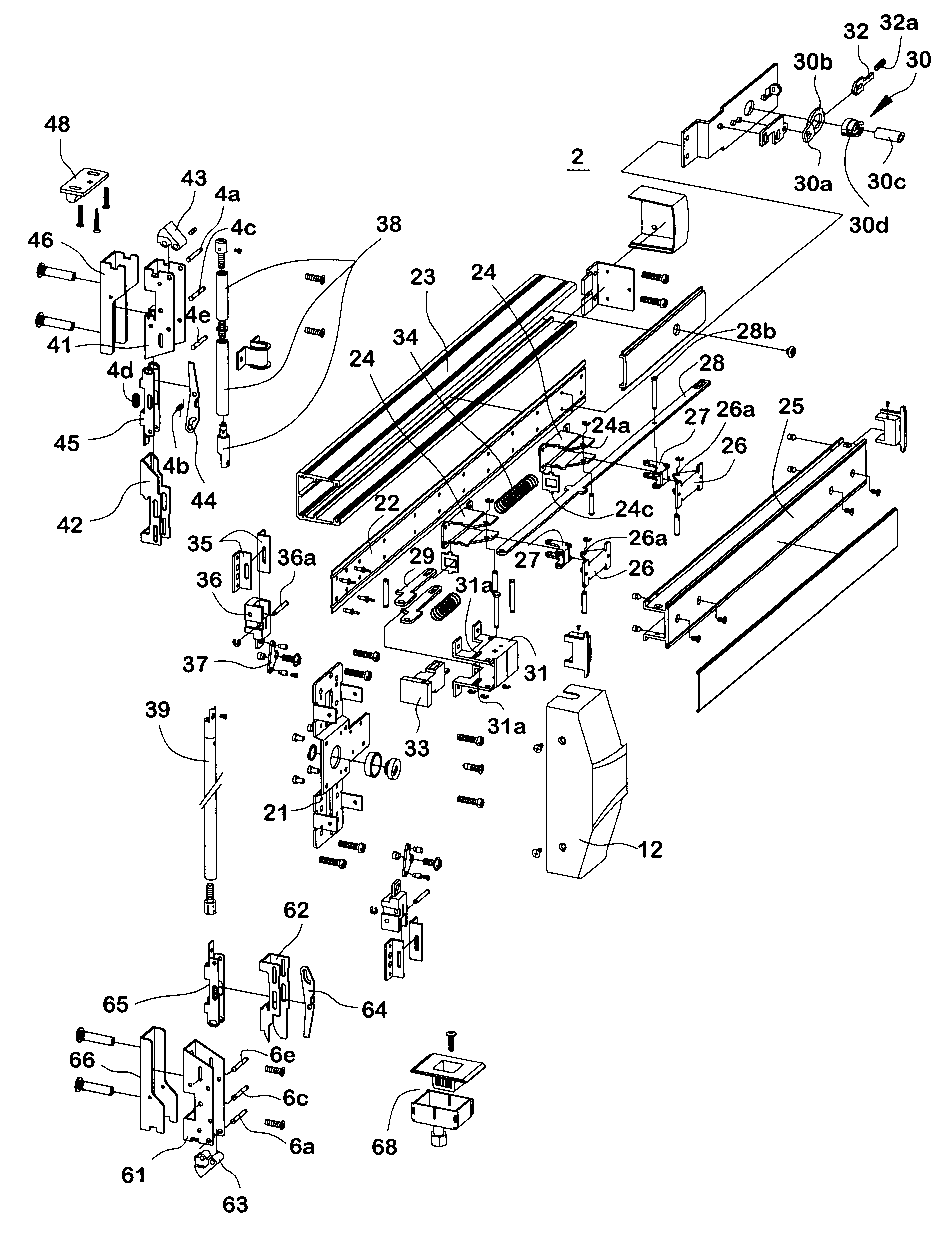
[0046]FIGS. 1 to 12 show preferred embodiments of the fire-blocking door lock structure of the present invention. The present invention enables a fire-blocking door 1 to comprise a frame member 10, a push handle 11, and a casing 12 forming a constituent body mounted on the fire-blocking door plank. The present invention provides a fire-blocking door lock structure 2 for being installed inside the constituent body on the fire-blocking door 1, the casing 12 has the bottom thereof mounted on a base body 21 and connected to a frame plate 22. The fire-blocking door lock structure 2 mainly comprises a middle latch mechanism 3, an upper latch mechanism 4, a lower latch mechanism 6 and an actuation mechanism 9.

[0047]The illustrative embodiments of the present invention are described using a fire-blocking door lock mounted on said constituent part. The present invention can be applicable to conventional fire-blocking doors without changing the structure of such kind of fire-blocking door, th...


PUM


Abstract

A fire-blocking door lock structure is mounted on a fire-blocking door including a frame member, a push handle and a casing. The casing has the bottom thereof fixed to a plate member and connected to a base body. The fire-blocking door lock structure includes a middle latch mechanism mounted in the casing, an upper latch mechanism and a lower latch mechanism symmetrically mounted on opposite sides of the middle latch mechanism and connected to the middle latch mechanism, and an actuation mechanism connected to the middle latch mechanism. When the push handle is pressed, the actuation mechanism is driven to actuate the middle latch mechanism, and the upper latch mechanism and the lower latch mechanism are simultaneously actuated by the middle latch mechanism to unlatch the door lock. When the push handle is released, the door lock is restored to the lock-up status.

Description

FIELD OF THE INVENTION[0001]The invention relates to fire-blocking door lock structures, and more particular, to a fire-blocking door lock suitable for a fire-blocking door, with concealed hinges formed on the top and bottom of the door lock.BACKGROUND OF THE INVENTION[0002]A general fire-blocking door lock structure is shown in FIGS. 13 and 14. Such fire-blocking door lock structure comprises a frame member 10 having a push handle 11, which is mounted on the frame member 10 for being pressed down by hand, and a casing 12 connected with a latch body 12d. [0003]As shown in the drawings that the push handle 11 is screwed and mounted on the bottom inside the frame member 10 and two fixed supports 13 are connected to the frame member 10 on the bottom inside. Two chutes 13a are installed on both sidewalls of fixed supports 13, respectively, for a sliding shaft 13b to be positioned in-between and fixed on the sidewalls of the push handle 11 by a pin 13c. Meanwhile, a spiral spring 13d is ...

Claims


Application Information

Patent Timeline
IPC IPC(8): E05B65/10E05B3/00
CPCE05B65/102Y10S292/65Y10T292/0908Y10T292/0909
Inventor LIN, CHING-TIEN
Owner LIN CHING TIEN
Learn More