Liquid jetting device and drive voltage correction method

a technology of liquid jetting device and drive voltage, which is applied in the direction of printing, inking apparatus, other printing apparatus, etc., can solve the problems of inability to achieve the desired image quality improvement, the deformation speed and the deformation rate of the actuator, and the adverse effect of high-definition image recording, etc., to achieve the effect of heightening the accuracy of the drive and improving the image quality

Active Publication Date: 2007-10-30
KONICA MINOLTA INC
View PDF1 Cites 4 Cited by
  • Summary
  • Abstract
  • Description
  • Claims
  • Application Information

AI Technical Summary

Benefits of technology

[0010]It is an object of the present invention to achieve the improvement of image quality by heightening the accuracy of a drive voltage correction.

Problems solved by technology

By the way, even if a drive signal of the same voltage value is applied to each nozzle, the deformation speeds and the deformation rates of the actuators are fluctuated owing to the individual differences of the nozzles, and the fluctuation has been an adverse effect of high-definition image recording as a result.
If a singular value of a small frequency is used for correction, an accurate correction cannot be performed, and the improvement of the image quality cannot be desired as a result.
Moreover, because there is the fluctuation between nozzles mentioned above also in the jetting quantity similarly in the jetting speed, there is the possibility that a value of a small frequency is used for a correction even in the case where a measured value is multiplied by a correction coefficient as in the liquid jetting device of JP-Tokukai-2004-90621A, and there has been a problem of the accuracy of a correction.
In particular, in the case where a singular value of a small frequency is used for a correction, the convergence of values takes a long time and further there is a possibility of diverging without converging even if the multiplication of the correction coefficient is performed.

Method used


Image

  • Liquid jetting device and drive voltage correction method
  • Liquid jetting device and drive voltage correction method
  • Liquid jetting device and drive voltage correction method

Examples


first embodiment

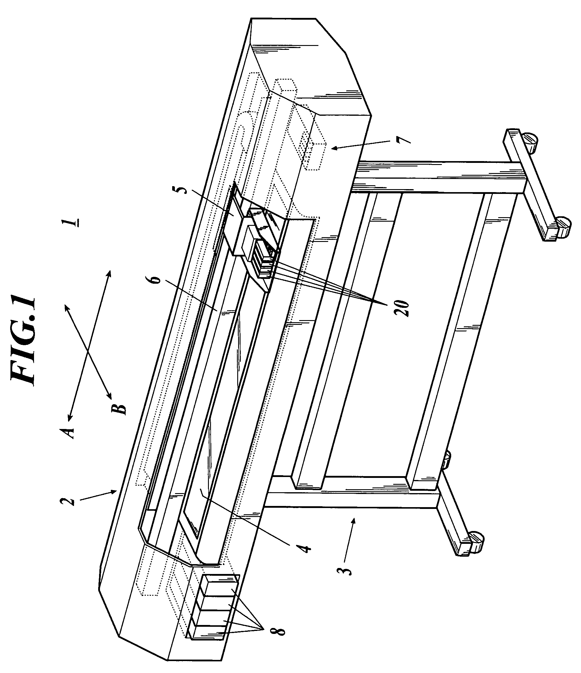
[0049]FIG. 1 is a perspective view showing the schematic configuration of an ink jet printer of a first embodiment to which a liquid jetting device according to the present invention is applied. As shown in FIG. 1, the ink jet printer 1 comprises a printer main body 2 and a supporting pedestal 3 supporting the printer main body 2 from the lower side. In the inside of the printer main body 2, a tabular platen 4 long in the lateral direction is provided. The platen 4 evenly supports a sheet-like recording medium from the lower side.

[0050]In FIG. 1, although the recording medium on which an image is recorded is not shown, the recording medium is fed in from a carry-in port formed on the back face of the printer main body 2, and passes the inside of the printer main body 2 from the back to the front in the state of being supported on the platen 4 by a conveyance mechanism, which is provided in a prescribed location in the inside of the printer main body 2, to be carried out to the outsi...

second embodiment

[0090]FIG. 9 is hereinafter referred to while a liquid jetting device according to the second embodiment is described. FIG. 9 is a flowchart showing a drive voltage correction method in the liquid jetting device according to the second embodiment. In the above-mentioned liquid jetting device according to the first embodiment, the drive voltage correction method in which correction is performed based on the correction voltage value acquired by adding the difference voltage value multiplied by the convergence coefficient to the drive voltage value at the time of measuring the jetting speed of an ink droplet has been described. But, in the second embodiment, a drive voltage correction method which can improve the accuracy of a drive voltage correction without using any convergence coefficient is described. In the following description, the same portions as those of the first embodiment are denoted by the same reference characters as those of the first embodiment, and the descriptions o...


PUM


Abstract

A liquid jetting device having: a recording head including a jetting energy generating element; a drive circuit generating drive signal for the element; a liquid detection sensor detecting a jetting characteristic value of liquid jetted from a nozzle; a drive voltage adjustment unit adjusting a voltage value of the drive signal; and a controller to control the drive circuit, the sensor and the drive voltage adjustment unit, wherein the controller performs control so that the liquid is jetted, and creates a correction data from the jetting characteristic value; and the controller performs control so that the voltage value is corrected based on a value obtained by multiplying the correction data by convergence coefficient within a range from 0.50 or more to less than 1.00, and repeats correcting the voltage value until a detection result of the liquid jetted based on the drive signal after the correction becomes a target value.

Description

BACKGROUND OF THE INVENTION[0001]1. Field of the Invention[0002]The present invention generally relates to a liquid jetting device and a drive voltage correction method for individual drop, and more particularly to a liquid jetting device and a drive voltage correction method used for an ink jet printer to set uniform droplet from all nozzles, a manufacturing apparatus coating a liquid material, and the like.[0003]2. Description of the Related Art[0004]An ink jet printer is generally known as an image recording apparatus recording an image on a recording medium such as paper. A liquid jetting device for jetting ink is installed in an ink jet printer, and the liquid jetting device is equipped with a recording head to jet the ink from a plurality of nozzles, and a drive circuit to drive the recording head.[0005]The recording head is equipped with a jetting energy generating element to each nozzle for jetting ink from each of the plurality of nozzles. As the jetting energy generating e...

Claims


Application Information

Patent Timeline
Patent Type & Authority Patents(United States)
IPC IPC(8): B41J29/38
CPCB41J2/0451B41J2/0456B41J2/04581B41J2/0459B41J2/12B41J2/125B41J2/16579B41J2/075B41J2202/10
Inventor URAKI, SHINGOKITAMI, AKIKOKOMATSU, KATSUAKI
Owner KONICA MINOLTA INC
Why Eureka
Try Eureka