Multifocal lens

a multi-focal lens and optical module technology, applied in the field of optical devices, can solve the problems that the lenses have not yet gained wide acceptance, and achieve the effects of reliable, inexpensive, and simple us

Inactive Publication Date: 2007-10-30
INVISIA
View PDF26 Cites 27 Cited by
  • Summary
  • Abstract
  • Description
  • Claims
  • Application Information

AI Technical Summary

Benefits of technology

[0008]Despite the long-felt need for effective multifocal contact lenses and intraocular lenses, such lenses have not yet gained wide acceptance. Embodiments of the present invention provide devices and techniques that overcome the limitations of the prior art and can thus be applied to produce multifocal lenses that are reliable, inexpensive, and simple to use, while affording correction of vision at multiple distances simultaneously.
[0010]In some of these embodiments, the focal modulation device is fabricated on an integrated circuit chip together with a controller and a photovoltaic power source. The entire chip is encapsulated within the lens body, and thus operates without any external source of power or control. In one embodiment, the focal modulation device comprises an array of liquid crystal cells, which are formed on the chip by a novel process. Recesses defining the liquid crystal cells are formed in the chip by photolithography. After injection of the liquid crystal material into the recesses, the cells are sealed with a polymer layer. This process obviates the need for a glass cover over the liquid crystal cells, and thus facilitates the creation of integrated liquid crystal devices that are thinner and less costly to produce than devices known in the art. This fabrication technique is useful not only in producing the multifocal lenses described herein, but also in other applications in which arrays of cells containing liquid crystal or other non-solid media are used.
[0011]In some embodiments of the present invention, the multifocal lens operates by switching rapidly between two or more focal states: a near-focus state, in which objects relatively close to the user's eye are focused on the retina; a distant-focus state, in which distant objects are in focus; and possibly one or more intermediate-focus states. The switching of focal depth occurs faster than the flicker-fusion frequency of the eye, so that the user is not consciously aware of the varying focal state. Such switching is typically accomplished by operation of the encapsulated optoelectronic focal modulation device described above, but it may alternatively be accomplished using other suitable means. The inventors have found that rapid switching of the focal state of the lens gives the user enhanced visual perception of both near and distant objects, in comparison with multifocal lenses known in the art that focus both near and far objects onto the retina simultaneously.
[0037]There is further provided, in accordance with an embodiment of the present invention, a method for enhancing vision of a user having an eye that includes a retina, the method including focusing light from objects in a field of view of the user onto the retina in alternation between at least first and second focal states that are characterized by different, respective first and second focal depths, at a rate of alternation that is in excess of a flicker-fusion frequency of the user.

Problems solved by technology

Despite the long-felt need for effective multifocal contact lenses and intraocular lenses, such lenses have not yet gained wide acceptance.

Method used


Image

  • Multifocal lens
  • Multifocal lens
  • Multifocal lens

Examples


Embodiment Construction

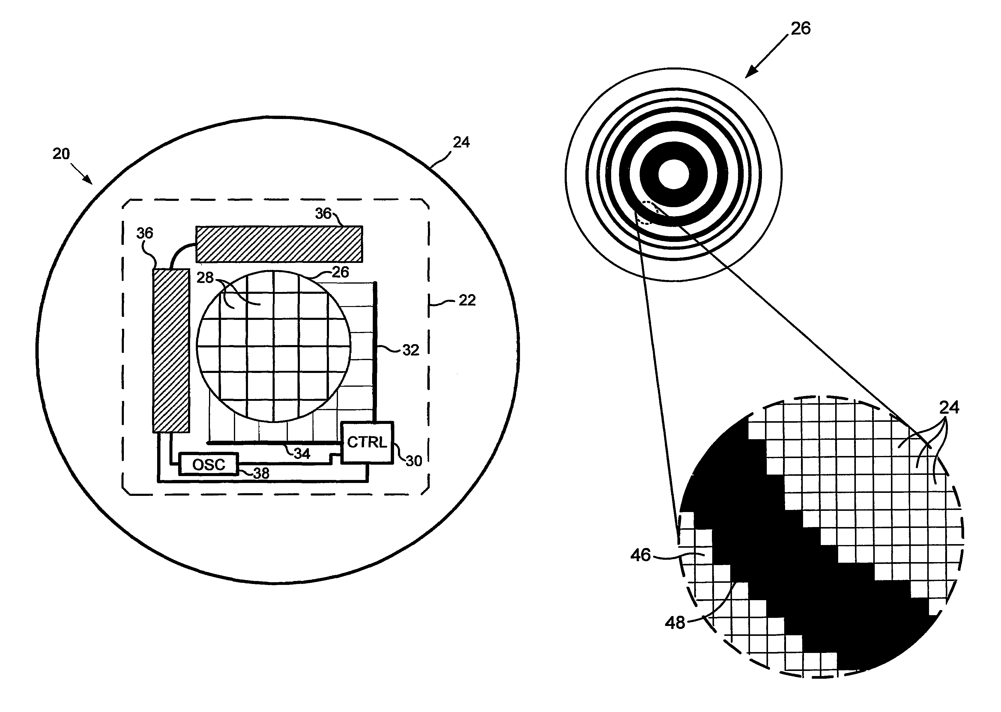
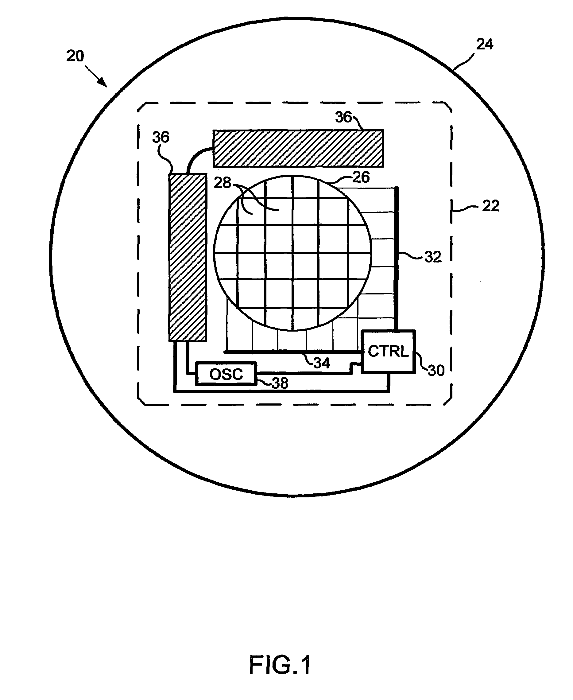
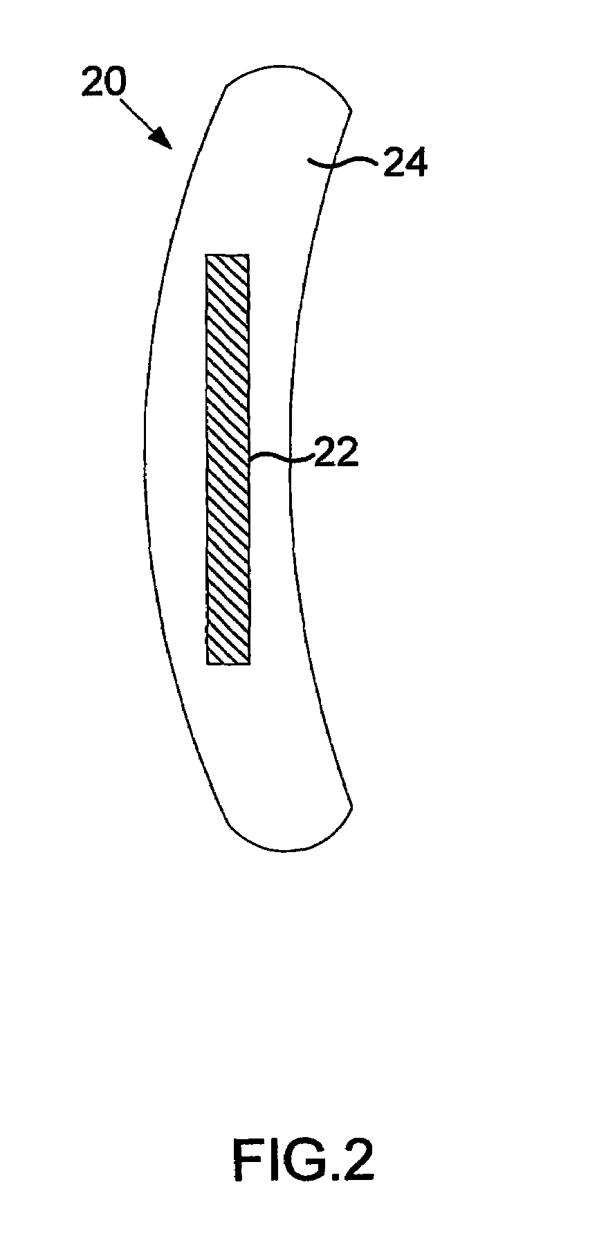
[0064]Reference is now made to FIGS. 1 and 2, which respectively show frontal and side views of an integrated multifocal lens 20, in accordance with an embodiment of the present invention. Lens 20 comprises an integrated focal modulation device 22, which is encapsulated in a lens body 24 made of a suitable optical material, such as glass or transparent plastic. In other embodiments, device 22 may be attached to the front or rear surface of such a lens body. Device 22 typically comprises a single integrated circuit chip, although multi-chip implementations are also possible, as described further hereinbelow. In this embodiment, lens 20 is made for use as a contact lens, but in alternative embodiments, described hereinbelow, focal control devices like device 22 may be encapsulated in lenses of other types, such as intraocular lenses and spectacle lenses, as shown in FIGS. 8 and 9 below.

[0065]Device 22 comprises a spatial light modulator (SLM) 26, which comprises an array of miniature ...


PUM

PropertyMeasurementUnit
threshold flicker-fusion frequencyaaaaaaaaaa
thickaaaaaaaaaa
focal depthsaaaaaaaaaa

Abstract

Apparatus for enhancing vision of a user includes a focal modulation device (22), which is adapted to focus light from objects in a field of view of the user onto the retina while alternating between at least first and second focal states that are characterized by different, respective first and second focal depths, at a rate in excess of a flicker-fusion frequency of the user.

Description

CROSS-REFERENCE TO PRIOR APPLICATION[0001]The above-referenced application is the U.S. National Phase of International Patent Application PCT / IL2004 / 000786 filed Aug. 30, 2004, which claims priority from U.S. Provisional Application Nos. 60 / 507,940 filed Oct. 3, 2003; 60 / 543,567 filed Feb. 12, 2004; and 60 / 582,552 filed Jun. 25, 2004, all of which are incorporated by reference herein. The International application was published in English on Apr. 14, 2005 as WO 2005 / 033782 A2 under PCT article 21(2).FIELD OF THE INVENTION[0002]The present invention relates generally to optical devices, and specifically to electronically-modulated multifocal lenses and methods for manufacture of such lenses.BACKGROUND OF THE INVENTION[0003]Accommodation enables a person of normal vision to focus on objects from infinity to a near point, typically of the order of 25 cm or less from the eye. Presbyopes lose the ability to accommodate over such a large range and typically require two or more corrections...

Claims


Application Information

Patent Timeline
Patent Type & Authority Patents(United States)
IPC IPC(8): G02F1/29G02C7/04G02C7/06G02F1/1335G02B3/14G02B26/02G02C7/08
CPCG02B3/14G02B26/004G02C7/06G02C7/083G02C7/101G02F1/136G02C2202/18H01L31/04G02F1/136277G02F2001/13324G02F2001/136281G02F2001/294G02F2203/12G09G3/001G02F1/13324G02F1/136281G02F1/294
Inventor KAUFMAN, MICHAKAUFMAN, KALMAN
Owner INVISIA
Why Eureka
Try Eureka