Reciprocating stroke bar bearing

Active Publication Date: 2007-11-06
HILTI AG
View PDF5 Cites 8 Cited by
  • Summary
  • Abstract
  • Description
  • Claims
  • Application Information

AI Technical Summary

Benefits of technology

[0006]The object of the present invention is to eliminate the aforesaid drawbacks and to reduce the manufacturing costs, while providing also satisfactory sealing of the gearing. According to the invention, this object is achieved in that bearing zones, over which the reciprocating movement transmitter saw is supported on the gearing housing at preferred advance direction of the saw all are arranged together in or on a carrying housing part.

Problems solved by technology

As a result, high material costs are incurred.
In addition, the assembly of the stroke bar guide system and the adjustment device between the two housing parts is relatively costly.
Furthermore, in the bearing method of the adjusting device provided here, complete sealing of the gearing housing to the outside can be achieved only with considerable difficulty.
Overall, high manufacturing costs are the result.

Method used


Image

  • Reciprocating stroke bar bearing
  • Reciprocating stroke bar bearing
  • Reciprocating stroke bar bearing

Examples


Embodiment Construction

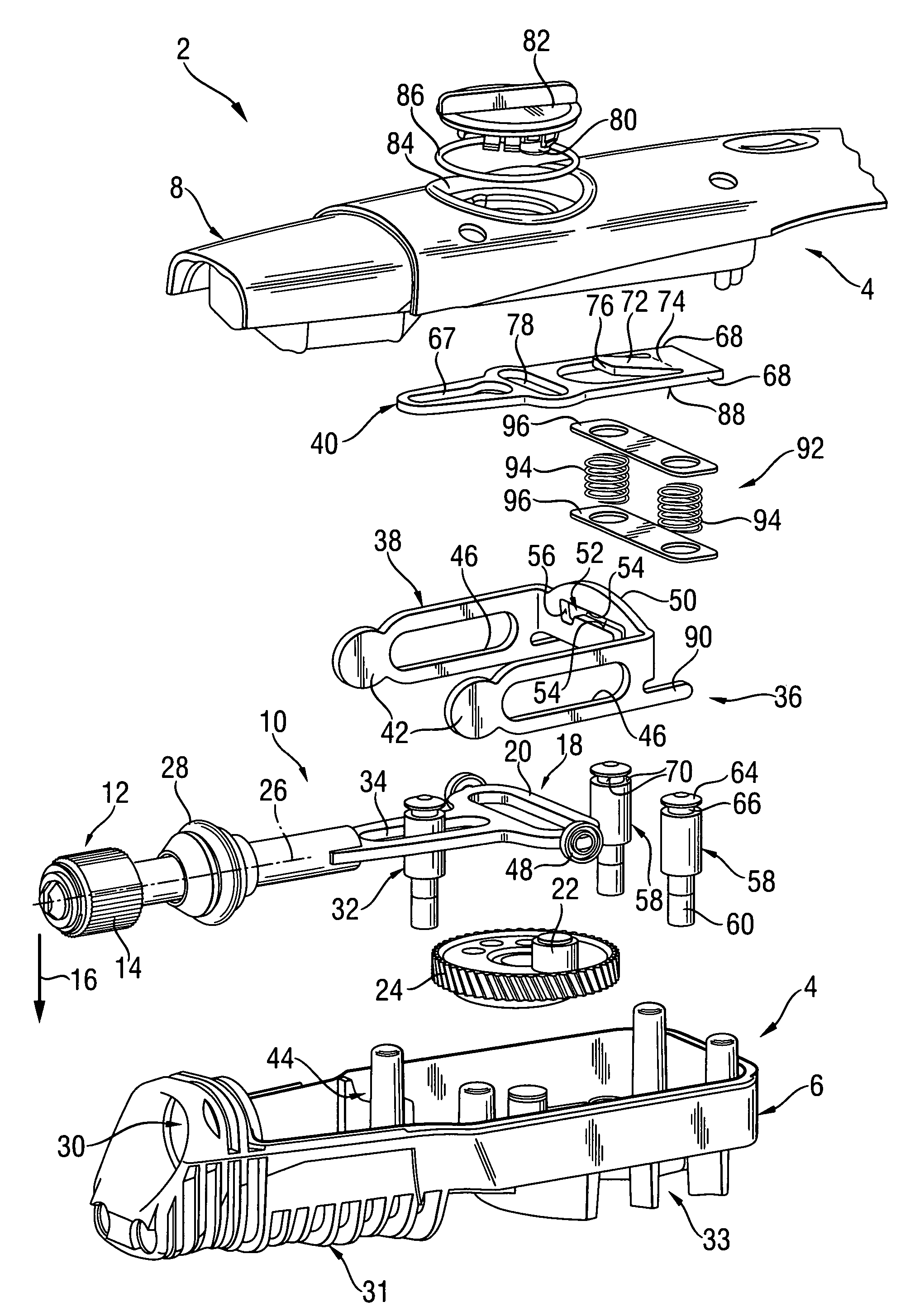
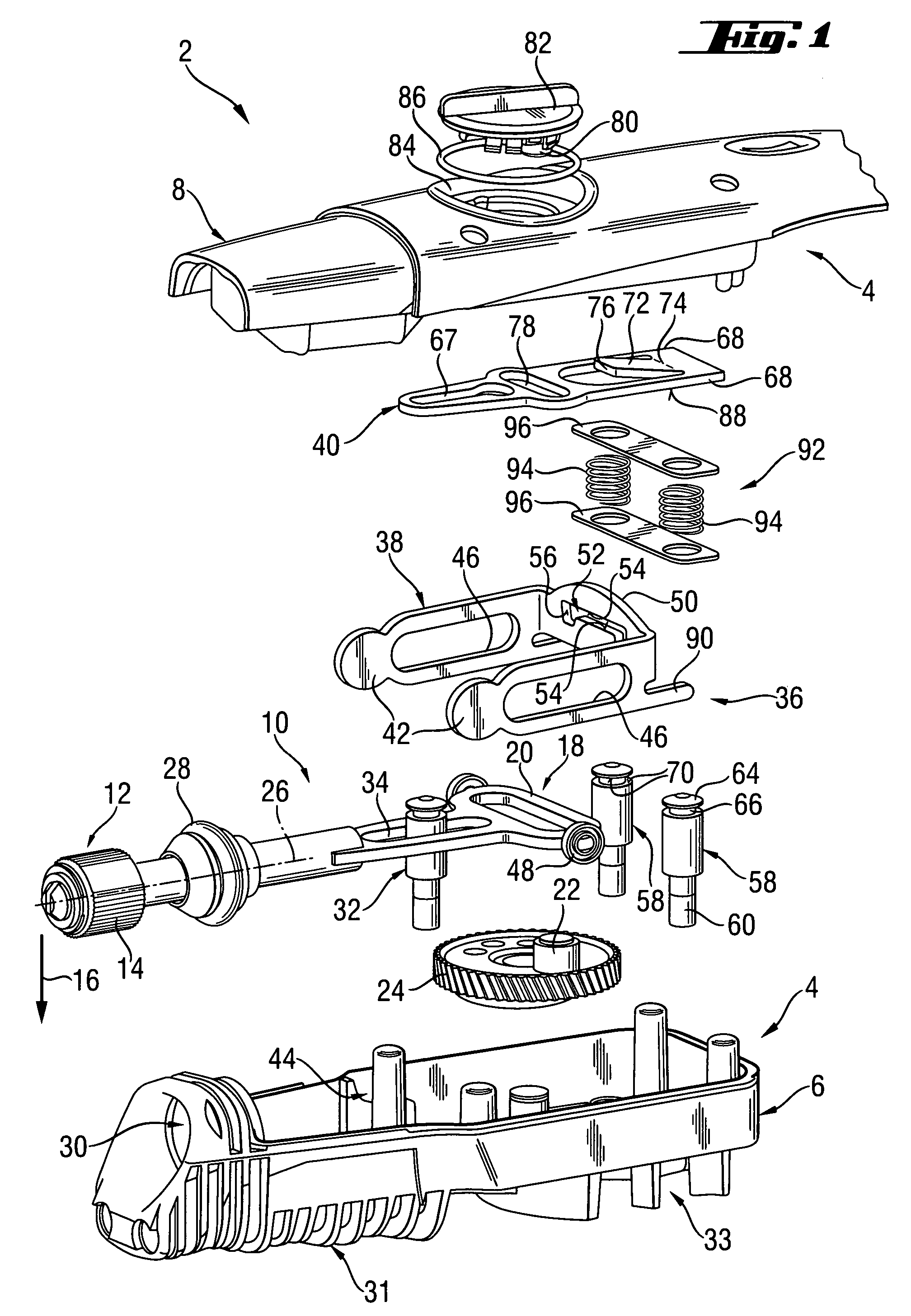
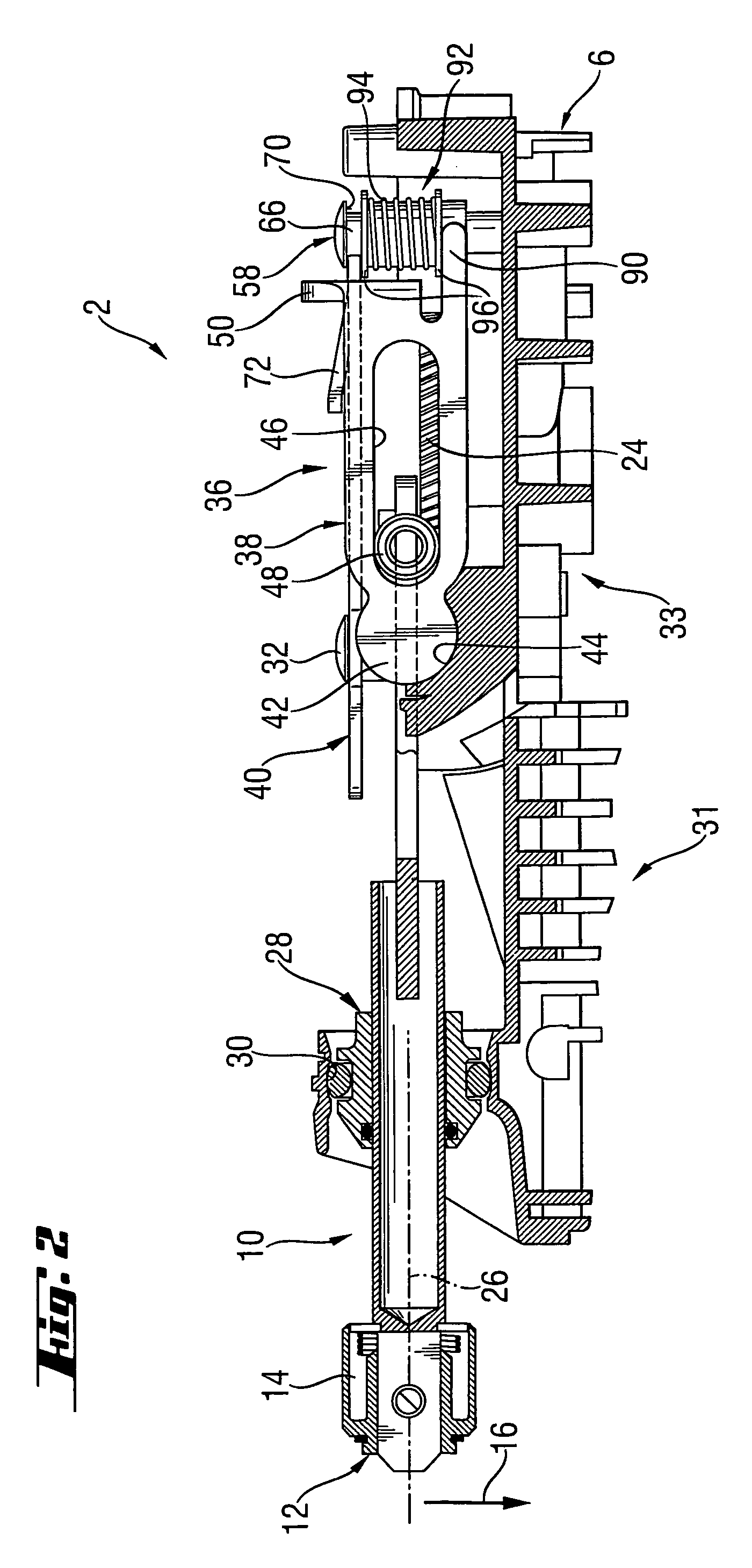
[0026]In the following, the terms “front”, “back”, “top” and “bottom” refer to an orientation of the saw, as shown in FIGS. 1 to 4, and to the orientation assumed by the saw, with it is held as intended by an operator. The designations “horizontal” and “vertical” refer to a stroke axis 26 assumed to be horizontal.

[0027]FIGS. 1 to 4 show gearing part 2 of a motor-driven saw such as a saber saw. The gearing part 2 has a gearing housing 4, which includes a carrying housing part 6 and a cover part 8 that are connected together at the time of assembly of the saw. The carrying housing part 6 is manufactured in an aluminum or magnesium pressure casting process. The cover part 8 is made of plastic.

[0028]The gearing part 2 has a stroke bar 10, at whose tool-side end 12 a tool receptacle 14 is provided. The tool receptacle 14 is used for fastening a tool (not shown) such as a saw blade, with which a work piece (not shown) can be worked. The arrow 16 indicates the preferred direction of advanc...


PUM

PropertyMeasurementUnit
Pressureaaaaaaaaaa
Displacementaaaaaaaaaa

Abstract

A motor-driven saw has a gearing housing (4), which has at least two housing parts (6, 8), a stroke bar (10), which in operation executes a stroke movement in the direction of a stroke axis (26), and a reciprocating movement generator (36) that can be turned on or off, by virtue of which the stroke movement is superimposed with a reciprocating movement executed transverse to the stroke axis (26). All bearing zones (30, 44, 62) over which the reciprocating movement generator (36) is supported on the gearing housing (4) in a preferred direction of advance (16) of the saw, are arranged in the same carrying housing part (6).

Description

BACKGROUND OF THE INVENTION[0001]The invention relates to a motor-driven saw having a gearing housing, which has at least two housing parts, a reciprocating rod, which when operating executes a reciprocating movement in the direction of a stroke axis, and an openable and closable reciprocating movement actuator, by which the stroke movement can be superimposed with a pendular movement made transverse to the stroke axis.[0002]Saws of this type are also known as “key-hole saws.” The reciprocating stroke movement of the saw produces an improved advance feed power principally when working on wood. In contrast, when working metal, the reciprocating stroke movement has certain drawbacks. Devices are known, in which the reciprocating movement can be changed or can be turned off to obtain a purely linear stroke movement.[0003]U.S. Pat. No. 6,212,781 discloses a saber saw with two housing halves with each accommodating a bearing bar of a stroke bar guide system. In this fashion, the stroke b...

Claims


Application Information

Patent Timeline
IPC IPC(8): B23D49/00B23D49/16B23D51/20B27B19/04
CPCB23D51/20B23D49/165Y10T83/7015Y10T83/9481
Inventor HARTMANN, MARKUS
Owner HILTI AG
Why Eureka
Try Eureka