Chemical heat source for use in smoking articles

a heat source and smoking technology, applied in the direction of heat exchange elements, tobacco, chemistry apparatus and processes, etc., can solve the problem of limited use of this heat source, and achieve the effect of more hea

Active Publication Date: 2007-11-06
R J REYNOLDS TOBACCO COMPANY
View PDF53 Cites 332 Cited by
  • Summary
  • Abstract
  • Description
  • Claims
  • Application Information

AI Technical Summary

Problems solved by technology

The use of this heat source was limited because it created an uncontrolled reaction and could sustain temperatures of about 100° C. in temperature.

Method used


Image

  • Chemical heat source for use in smoking articles
  • Chemical heat source for use in smoking articles
  • Chemical heat source for use in smoking articles

Examples


example 1

[0092]A heat chamber is prepared as follows:

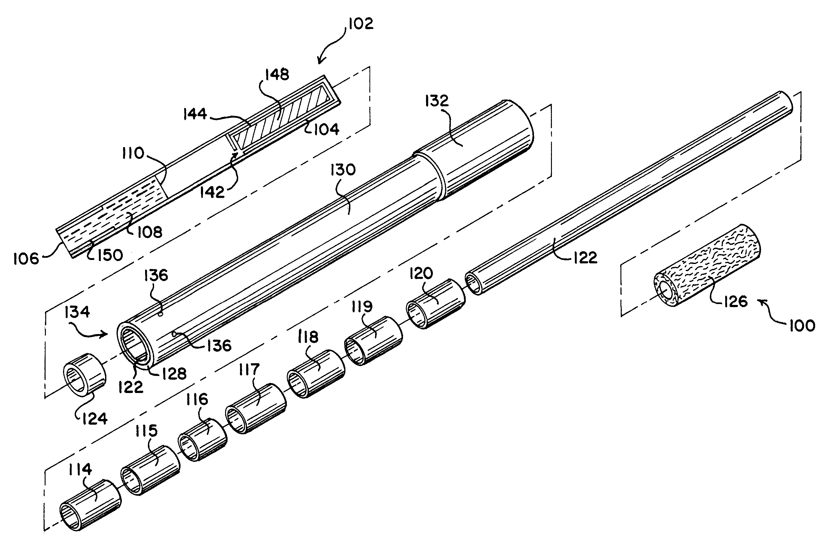
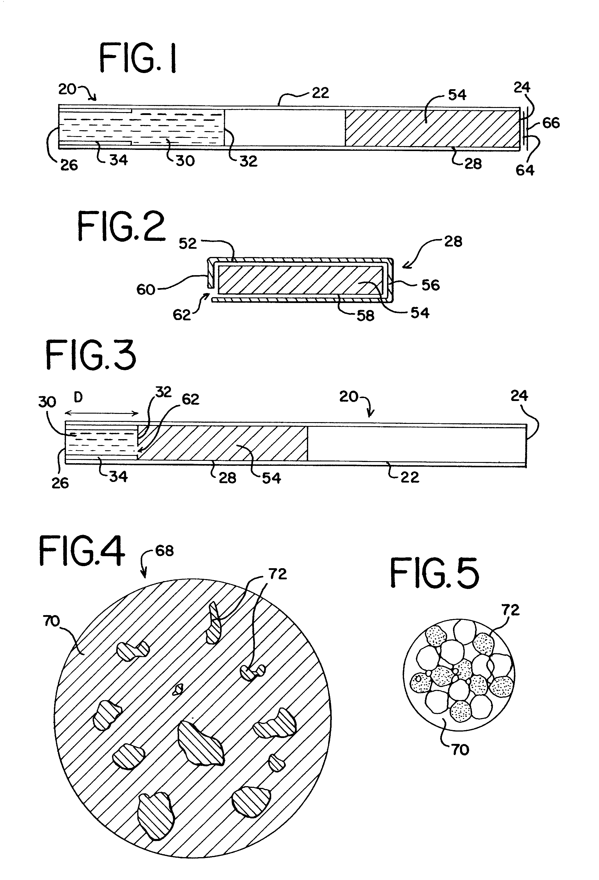
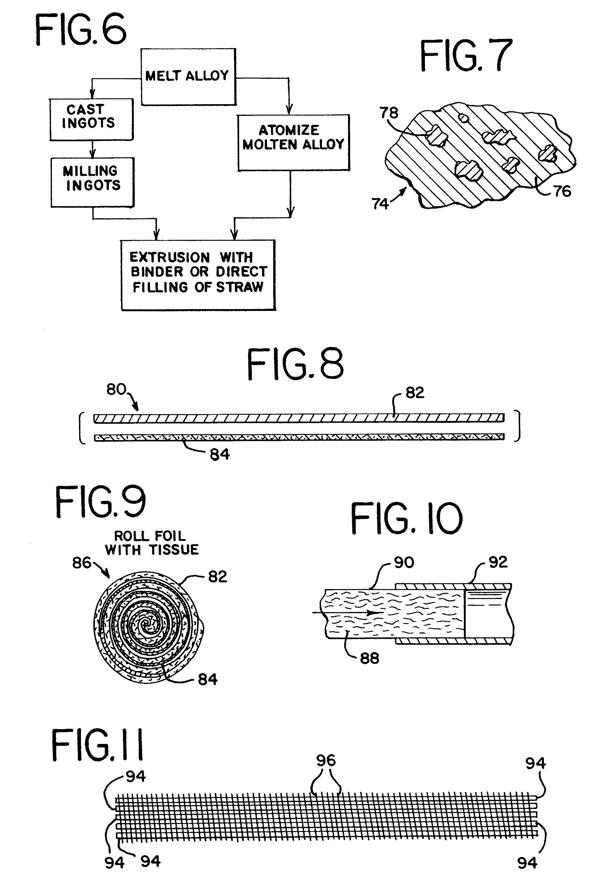
[0093]The heat chamber is made of a special grade of polypropylene, available from The Dow Chemical Company, which can withstand at least 200° C. The chamber is a 105 mm long polypropylene tube with an internal diameter of 4.72 mm. Extruded tubes of this dimension can be obtained from American Extruded Plastic, Greensboro, N.C. The tubes are cut to appropriate length and one end is heat-sealed using an electric hot plate. A 20 mm long Mylar® tube with an internal diameter of 4.72 mm is cut longitudinally in half. The longitudinally cut piece of Mylar® tube is placed at the closed end of the heat chamber. This serves as a stopper for the heat cartridge when it is pushed through a frangible seal.

example 2

[0094]A heat cartridge is prepared as follows:

[0095]The heat cartridge is prepared from a tube made of porous plug wrap 0011417. Porous plug wrap 0011417 is supplied by Schweitzer, Mauduit International Inc., Alpharetta, Ga. (SWM), with 6650 Coresta Units (CU) porosity, 20.5 g / m2 basis weight, and 0.0540 mm caliper. Plug wraps with lower porosity can be used, provided the porosity is increased to the described level by mechanical perforation. Alternative plug wraps include: 0016361 supplied by Miquel (MYC), which has a porosity of 1570 CU, basis weight 22 g / m2, and caliper of 0.0425 mm; 0011745 supplied by SWM, which has a porosity of 26,000 CU, basis weight of 22 g / m2, and caliper of 0.0650 mm; 1001622 supplied by SWM, which has a porosity of 4375 CU, a basis weight of 22 g / m2, and caliper of 0.0516 mm. All of these are available in 26.5 mm. width.

[0096]A rectangular piece of the plug wrap 0011417, 17 mm by 43 mm, is rolled into a tube with an internal diameter of 0.1465 inch (3.72...

example 3

[0098]A heat cartridge is prepared as follows:

[0099]A rectangular piece of multipurpose 20 lb paper, Hewlett Packard, 26 mm by 40 mm, is rolled into a tube having an internal diameter of 0.1465 inch (3.72 mm). The paper is held in place with a thin glue line. About 4 mm length of the tube is folded and glued to form the closed end of the cartridge. About 350 mg of metallic agent, Corrodalloy 5 from Dymatron, Inc., is covered with a 10 mm by 12 mm piece of Kleenex® tissue and is placed inside the tube. The tube is then folded shut leaving a 2.5 mm opening. The end of the cartridge with the opening forms the bottom of the cartridge. The outer diameter of the cartridge is such that it closely fits inside the heat chamber of Example 1.


PUM

PropertyMeasurementUnit
temperatureaaaaaaaaaa
temperaturesaaaaaaaaaa

Abstract

A non-combustion, chemical heat source includes a heat chamber having a closed end and an open end. The heat chamber includes an apertured heat cartridge disposed at the open end of the chamber, an abutment disposed at the closed end of the chamber, an activating solution, a frangible seal separating the activating solution and the heat cartridge. The heat cartridge includes metallic agents that may come in a variety of configurations. The heat source is activated when the heat cartridge is pushed through and breaks the frangible seal allowing contact between the metallic agents and the activating solution. The heat cartridge includes an aperture in the bottom of the cartridge and absorbent paper surrounding the metallic agents, both of which control the transfer of the activating solution into the metallic agents to cause the chemical reaction. The heat sources may be incorporated into smoking articles and may also be used to heat foods or beverages, in hand warmers, and to heat equipment or materials.

Description

BACKGROUND OF THE INVENTION[0001]The present invention relates to non-combustion chemical heat sources, such as electrochemical heat sources, materials used to make chemical heat sources, and methods of forming chemical heat sources. Specifically, the present invention relates to a heat source used in a smoking article to heat tobacco, thereby producing a tobacco flavor or tobacco-flavored aerosol.[0002]The heat sources of the present invention are particularly adapted for use in smoking articles that are capable of providing the user with the pleasures of smoking (e.g., smoking taste, feel, satisfaction, and the like), without burning tobacco or any other material, without producing sidestream smoke or odor, and without producing combustion products such as carbon monoxide. As used herein, the term “smoking article” includes cigarettes, cigars, pipes, and the like, which use tobacco in various forms.[0003]Smoking articles have had various shapes, and have been composed of various t...

Claims


Application Information

Patent Timeline
Patent Type & Authority Patents(United States)
IPC IPC(8): A24F1/22A24F42/10A24F42/60A24F42/80C09K5/18
CPCA24B15/16C09K5/18A24F47/006A24F42/10A24F42/80A24F42/60
Inventor BANERJEE, CHANDRA KUMARCASH, SHEILA LYNNETTEGENTRY, THOMAS LEEROYTAYLOR, JOANNE NAOMITURNER, PATTY FERGUSON
Owner R J REYNOLDS TOBACCO COMPANY
Why Eureka
Try Eureka