Hydraulic steering mechanism and driving-steering-wheel support mechanism

Active Publication Date: 2007-11-06
KANZAKI KOKYUKOKI MFG
View PDF14 Cites 15 Cited by
  • Summary
  • Abstract
  • Description
  • Claims
  • Application Information

AI Technical Summary

Benefits of technology

[0019]In another embodiment, instead of or in addition to the lower bearing fixing member, the driving-steering-wheel support mechanism may further include a second upward step provided to the turning portion so as to be engaged with a lower surface of the outer ring of the lower bearing; a spacer extending between the upper bearing and the lower bearing; and

Problems solved by technology

However, in the conventional hydraulic steering mechanism, sufficient consideration has

Method used


Image

  • Hydraulic steering mechanism and driving-steering-wheel support mechanism
  • Hydraulic steering mechanism and driving-steering-wheel support mechanism
  • Hydraulic steering mechanism and driving-steering-wheel support mechanism

Examples


embodiment 1

[0032]Hereinafter, description will be made on a preferred embodiment of the present invention with reference to the accompanying drawings.

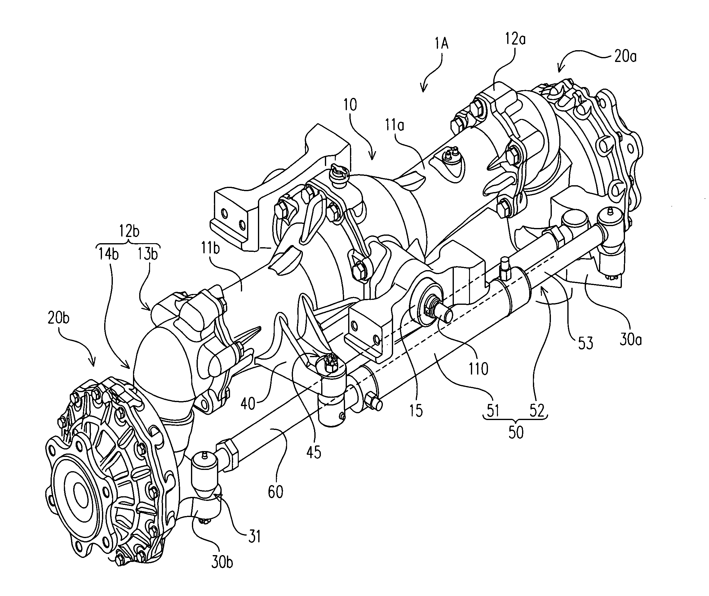
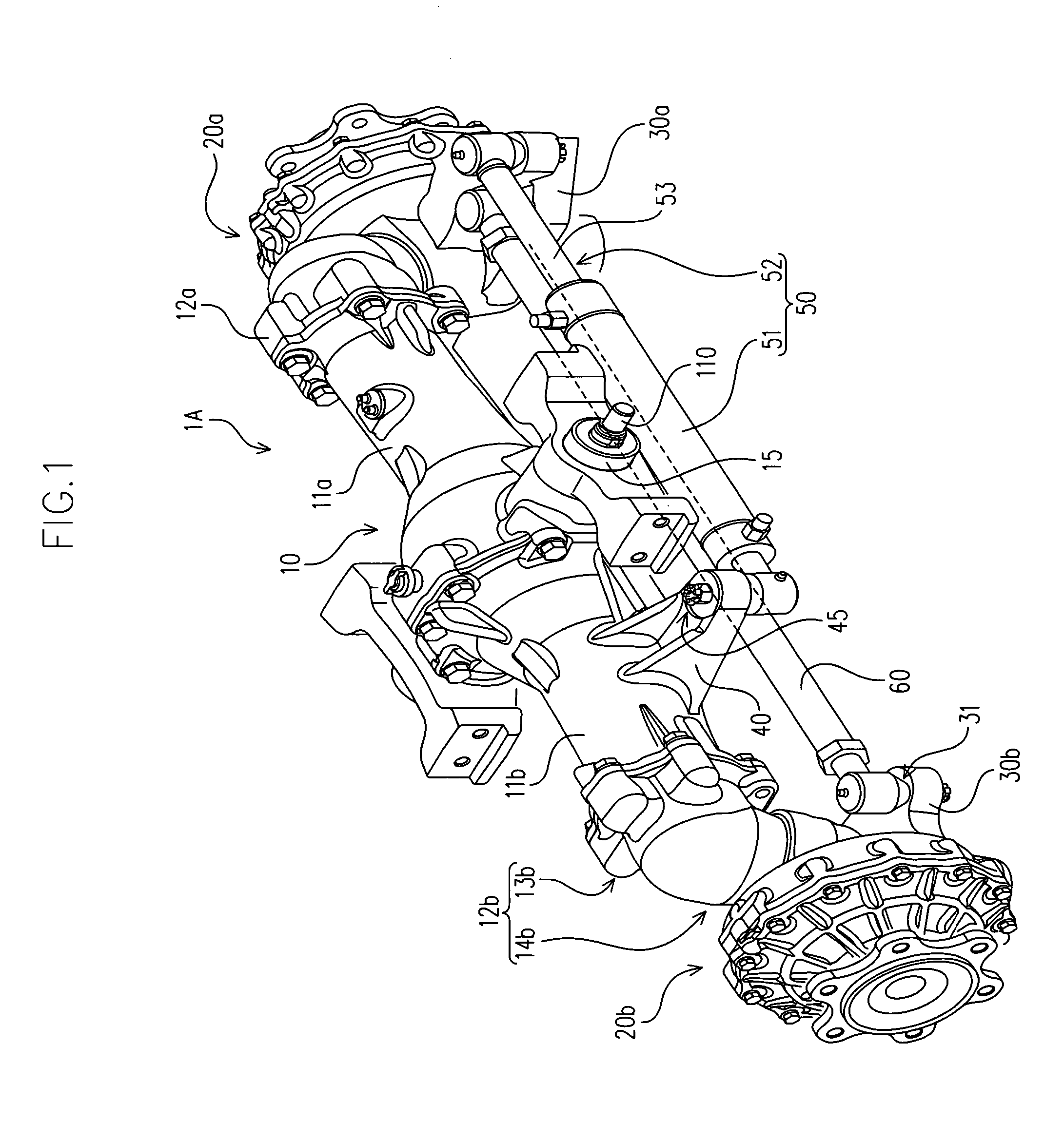
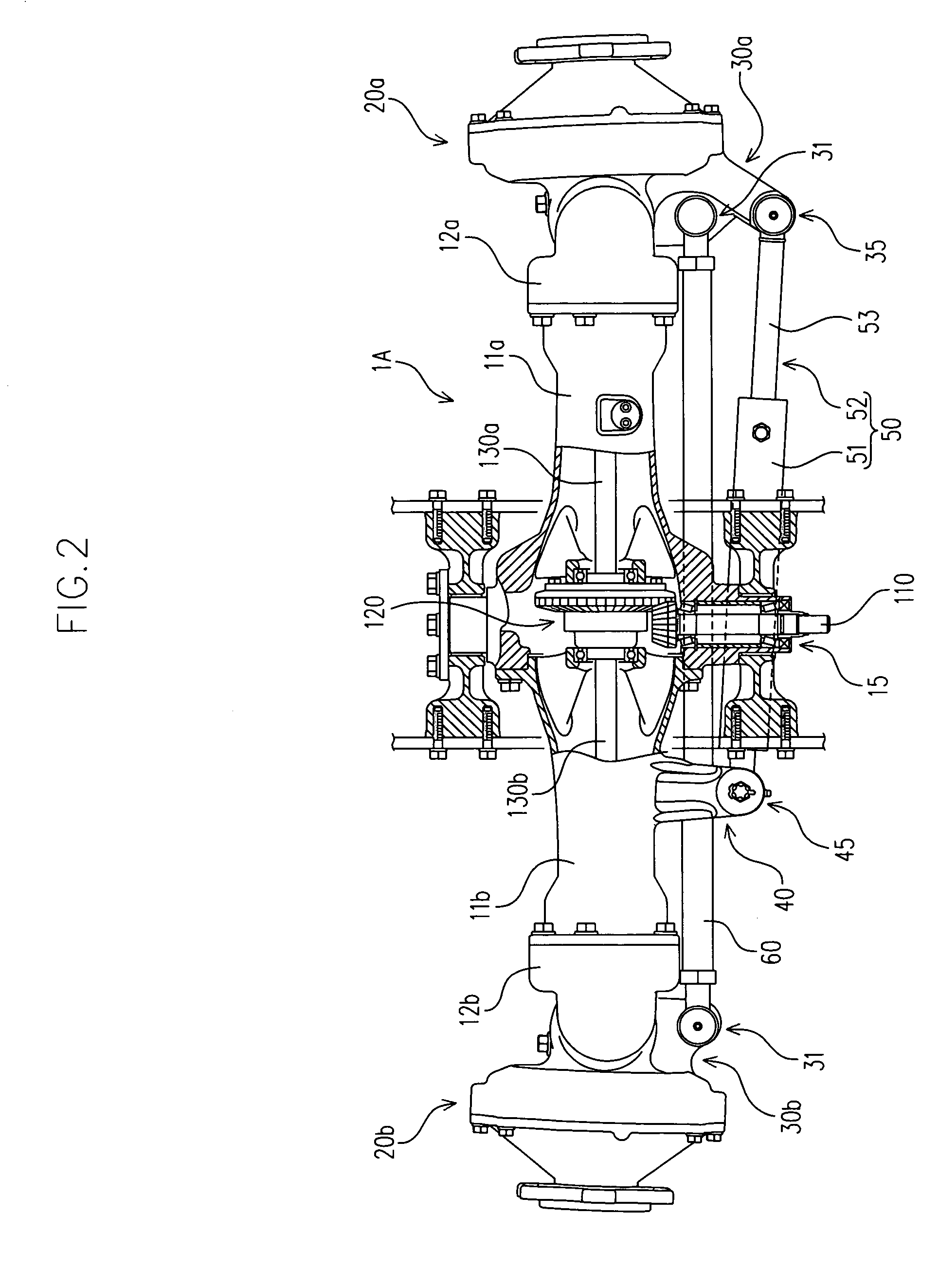
[0033]FIG. 1 is a perspective view of a hydraulic steering mechanism 1A according to this embodiment when viewed diagonally from behind. FIGS. 2 and 3 are respectively a partial cross-sectional plan view and a back view of the hydraulic steering mechanism 1A according to this embodiment.

[0034]As shown in FIGS. 1 to 3, the hydraulic steering mechanism 1A according to this embodiment includes an axle case 10, first and second steering cases 20a and 20b respectively provided to both ends of the axle case in a longitudinal direction, first and second arms 30a and 30b respectively provided to first and second steering cases 20a and 20b, a third arm 40 provided to the axle case 10, a hydraulic actuator 50 including a cylinder 51 and a piston 52, and a tie rod 60 for interlocking and linking the first and second steering cases 20a and 20b with and to ea...

embodiment 2

[0107]Hereinafter, description will be made on another preferred embodiment of the present invention with reference to FIGS. 7 and 8.

[0108]FIG. 7 is a vertical sectional back view of a vicinity of a fixed case in a hydraulic steering mechanism 1B according to this embodiment. FIG. 8 is an exploded vertical sectional back view of the fixed case and a steering case.

[0109]In the drawings, members similar or corresponding to those in the first embodiment are provided with the same reference numerals; therefore, description thereof will not be made.

[0110]The hydraulic steering mechanism 1B according to this embodiment is different from the first embodiment only in that the structure for preventing withdrawal of the first steering case 20a from the first fixed case 12a and is substantially the same in other structures.

[0111]In other words, the hydraulic steering mechanism 1B according to this embodiment includes a spacer 76 extending between the upper bearing 210 and the lower bearing 220...


PUM


Abstract

The hydraulic steering mechanism according to the present invention includes an axle case, a first steering case, a second steering case, a first arm, a second arms, a third arm, a hydraulic actuator, and a tie rod. The first, second and third arms are provided to the first steering case, the second steering case and the axle case, respectively. The hydraulic actuator includes a cylinder and a piston for moving with respect to each other by an action of hydraulic pressure. The first and second arms have tie rod mounting portions to which the tie rod is mounted. At least one of the first and second arms has a first hydraulic actuator mounting portion to which one of the cylinder and the piston in the hydraulic actuator is mounted. The third arm has a second hydraulic actuator mounting portion to which the other of the cylinder and the piston in the hydraulic actuator is mounted. The first hydraulic actuator mounting portion is at a longer distance from axis lines of the differential yoke shafts than the second hydraulic actuator mounting portion in a plan view when the vehicle is traveling substantially straight.

Description

BACKGROUND OF THE INVENTION[0001]1. Field of the Invention[0002]The present invention relates to a hydraulic steering mechanism for steering drive wheels by utilizing hydraulic pressure.[0003]2. Related Art[0004]There is conventionally known a hydraulic steering mechanism for steering a pair of drive wheels by connecting a pair of steering cases that are disposed at both ends of an axle case through a tie rod and by turning one of the steering cases about a kingpin shaft by a hydraulic actuator.[0005]However, in the conventional hydraulic steering mechanism, sufficient consideration has not been given to a viewpoint of a reduction in steering force of the hydraulic actuator.[0006]The present invention has been accomplished with the above conventional technique in view, and it is an object of the invention to provide a hydraulic steering mechanism with a simple structure in which a hydraulic actuator for turning a steering case about a kingpin shaft can be miniaturized.SUMMARY OF THE...

Claims


Application Information

Patent Timeline
IPC IPC(8): B62D5/06B62D5/10B62D7/16B60K17/30B62D7/08B62D7/18B62D7/20B62D9/00
CPCB62D7/18B60K17/303
Inventor NAGATA, KENTAROTOTTORI, HIROSHITSUKAMOTO, MICHIOISHII, NORIHIRO
Owner KANZAKI KOKYUKOKI MFG
Why Eureka
Try Eureka