Pipe clip

a pipe clip and wing nuts technology, applied in the field of pipe clips, can solve the problems of time-consuming, difficult mounting/disassembly of the pipe clip, and substantial human labor in tightening the wing nuts, and achieve the effect of reducing time-consuming and labor-intensive, efficient installation and avoiding drawbacks

Inactive Publication Date: 2007-11-06
HIGHLIGHT TECH
View PDF13 Cites 50 Cited by
  • Summary
  • Abstract
  • Description
  • Claims
  • Application Information

AI Technical Summary

Benefits of technology

[0008]The primary purpose of the present invention is to eliminate the drawbacks of the conventional device, including tightening a number of bolts that extend through aligned holes defined in opposing end flanges of pipe sections to be jointed or tightening a bolt-wing nut pair that secures two clipping members that rotate with respect to each other, both being very time-consuming and labor-intensive, the present invention is aimed to provide a pipe clip comprising upper and lower clip members that are pivoted at one end and form upper and lower slots with a locking bar fixed in the lower slot. The upper and lower clip members form upper and lower grooves for receiving and thus engaging flanges of pipe sections to be joined therein. A U-shaped pull tab has two limbs fit over and pivoted to the upper slot. An abutting block rotates and is fixed between the limbs and defines a through hole through which a stem of a hook-on member slides while extending. The hook-on member has a hooked end which engages with the locking bar. A helical spring is fit over the stem and retained between the abutting block and a nut engaging a threaded end of the stem. The clip is efficiently installed by engaging the hooked end of the hook-on member with the locking bar and can be secured and released by pushing / pulling the pull tab. The pull tab is configured to causes deformation of the spring to induce a torque against release of the pull tab from the secured position.

Problems solved by technology

However, it is very time consuming if the number of bolt-nut pairs used to joint the pipe section is great.
The conventional pipe clip is disadvantageous in that substantial human labor is needed in tightening the wing nuts.
This renders mounting / dismounting the pipe clip difficult and is a time-consuming process.
In addition, repeated tightening / loosening causes fatigue of the thread of the bolt or nut and once the threaded is broken, the pipe clip is useless and has to be replaced.

Method used


Image

  • Pipe clip
  • Pipe clip
  • Pipe clip

Examples


Embodiment Construction

[0023]The following descriptions are of exemplary embodiments only, and are not intended to limit the scope, applicability or configuration of the invention in any way. Rather, the following description provides a convenient illustration for implementing exemplary embodiments of the invention. Various changes to the described embodiments may be made in the function and arrangement of the elements described without departing from the scope of the invention as set forth in the appended claims.

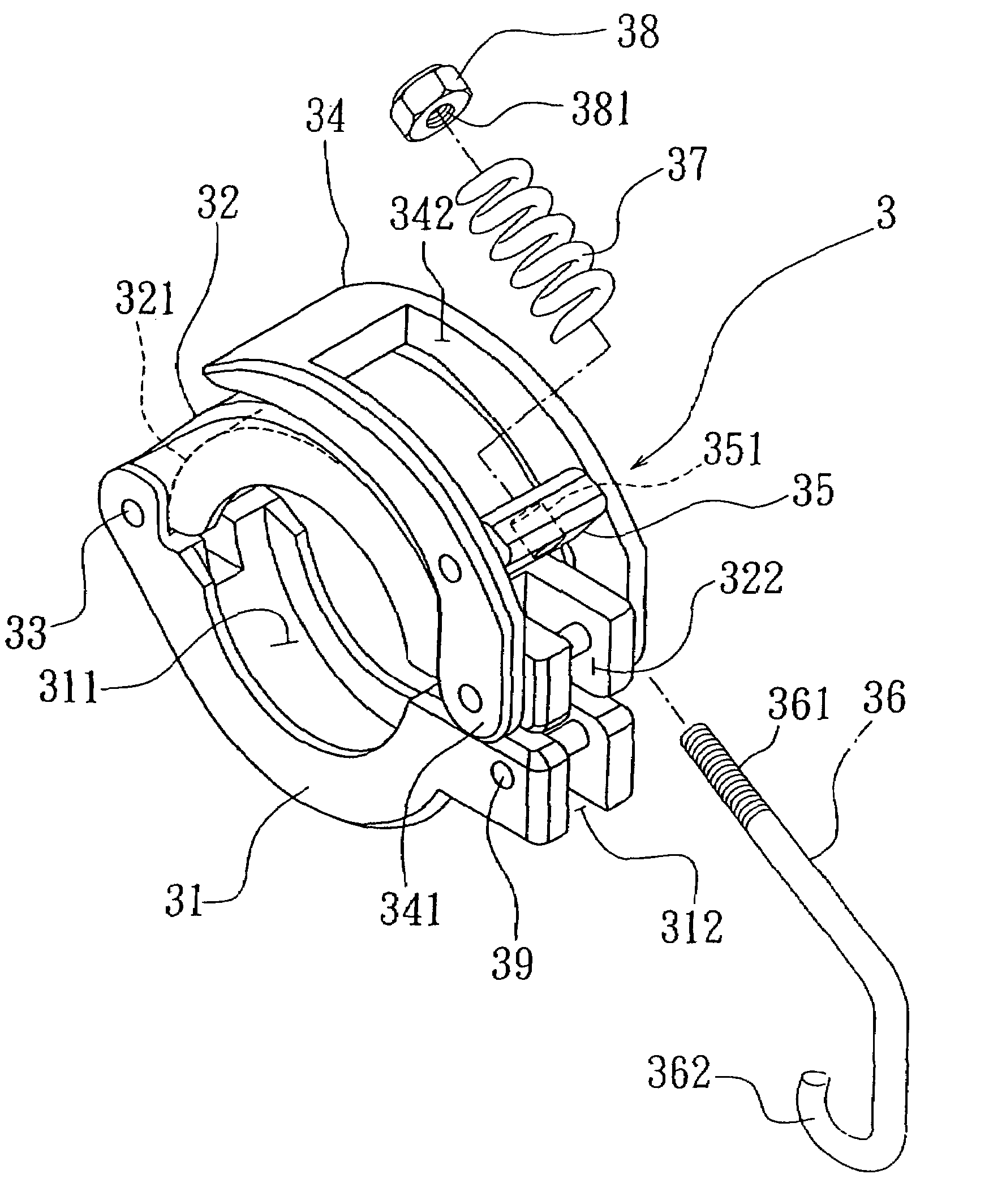
[0024]With reference to the drawings and in particular to FIGS. 7-10, a pipe clip constructed in accordance with the present invention, generally designated with reference numeral 3, comprises a lower clip member 31, an upper clip member 32, a pull tab 34, an abutting block 35, a resilient element 37, a retention member 38, and a releasable hook-on member 36. The upper and lower clip members 31, 32 form, in an inside face thereof, flange-receiving grooves 311, 321 for receiving and engaging end f...


PUM


Abstract

A pipe clip includes upper and lower clip members that are pivoted at one end and form upper and lower slots with a locking bar fixed in the lower slot. The upper and lower clip members form upper and lower grooves for receiving and thus engaging flanges of pipe sections to be jointed therein. A U-shaped pull tab has two limbs fit over and pivoted to the upper slot. An abutting block is fixed while rotating between the limbs and defines a through hole through which a stem of a hook-on member extends by sliding. The hook-on member has a hooked end engaged with the locking bar. A helical spring is fit over the stem and retained between the abutting block and a nut engaging a threaded end of the stem. The clip is efficiently installed by engaging the hooked end of the hook-on member with the locking bar and can be secured and released by pushing / pulling the pull tab. The pull tab is configured to causes deformation of the spring to induce a torque against release of the pull tab from the secured position.

Description

BACKGROUND OF THE INVENTION[0001](a) Technical Field of the Invention[0002]The present invention generally relates to a pipe clip for joining two separate pipes having opposing end flanges, and in particular to a pipe clip comprised of a rotating upper and lower clip members that are release-secured together by a spring-biased hook-on member for efficient installation and compensation for fatigue of parts.[0003](b) Description of the Prior Art[0004]FIG. 1 of the attached drawings shows a conventional way for joining two sections of pipe with bolts. Each pipe section, which is designated with reference numeral 1 in the drawings, is formed with a flange 11 around an end thereof. Aligned holes are defined in the flanges 11 to receive bolts 12 that engage nuts 13 to apply a force that fixes the flanges 11 together. This construction has been widely used to join two pipe sections. However, it is very time consuming if the number of bolt-nut pairs used to joint the pipe section is great.[...

Claims


Application Information

Patent Timeline
Patent Type & Authority Patents(United States)
IPC IPC(8): F16L17/00
CPCF16L23/06
Inventor WU, MING-TIEN
Owner HIGHLIGHT TECH
Why Eureka
Try Eureka