Dust extractor device for a router

a dust extractor and router technology, applied in the direction of woodworking safety devices, metal-working machine components, manufacturing tools, etc., can solve the problems of comparatively bulky dust extractor devices, high price, etc., and achieve the effect of maximum effectiveness

Active Publication Date: 2007-11-06
FESTOOL GMBH
View PDF16 Cites 75 Cited by
  • Summary
  • Abstract
  • Description
  • Claims
  • Application Information

AI Technical Summary

Benefits of technology

[0005]Accordingly one object of the present invention is to provide a dust extractor device with maximum effectiveness as regards the aspiration or extraction of dust.
[0006]A further object of the invention is to provide such a dust extractor device requiring comparatively little space and whose design is as simple as possible.
[0008]It is in this manner that the aspiration or extraction of dust takes place through the central access opening in the foot plate so that, possibly with the exception of the connection means, a space saving arrangement is possible without parts projecting past the foot plate. The top covering means prevents escape of router dust or the like upward so that the router dust is reliably passed to the connection means and thence into the aspiration hose. It is a question here of simple and economic components.

Problems solved by technology

The known dust extractor device is furthermore comparatively bulky and is high in price.

Method used


Image

  • Dust extractor device for a router
  • Dust extractor device for a router
  • Dust extractor device for a router

Examples


Embodiment Construction

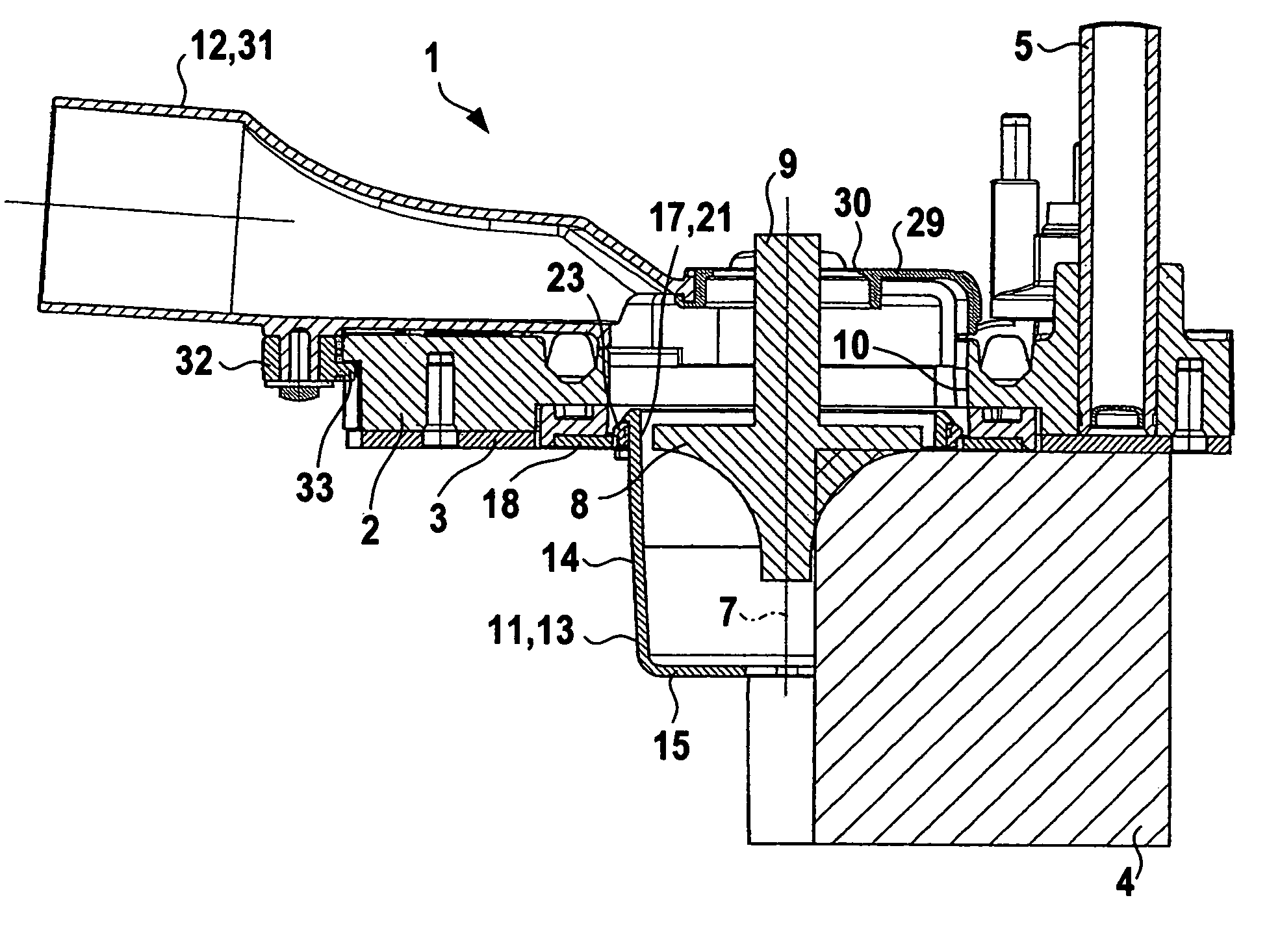
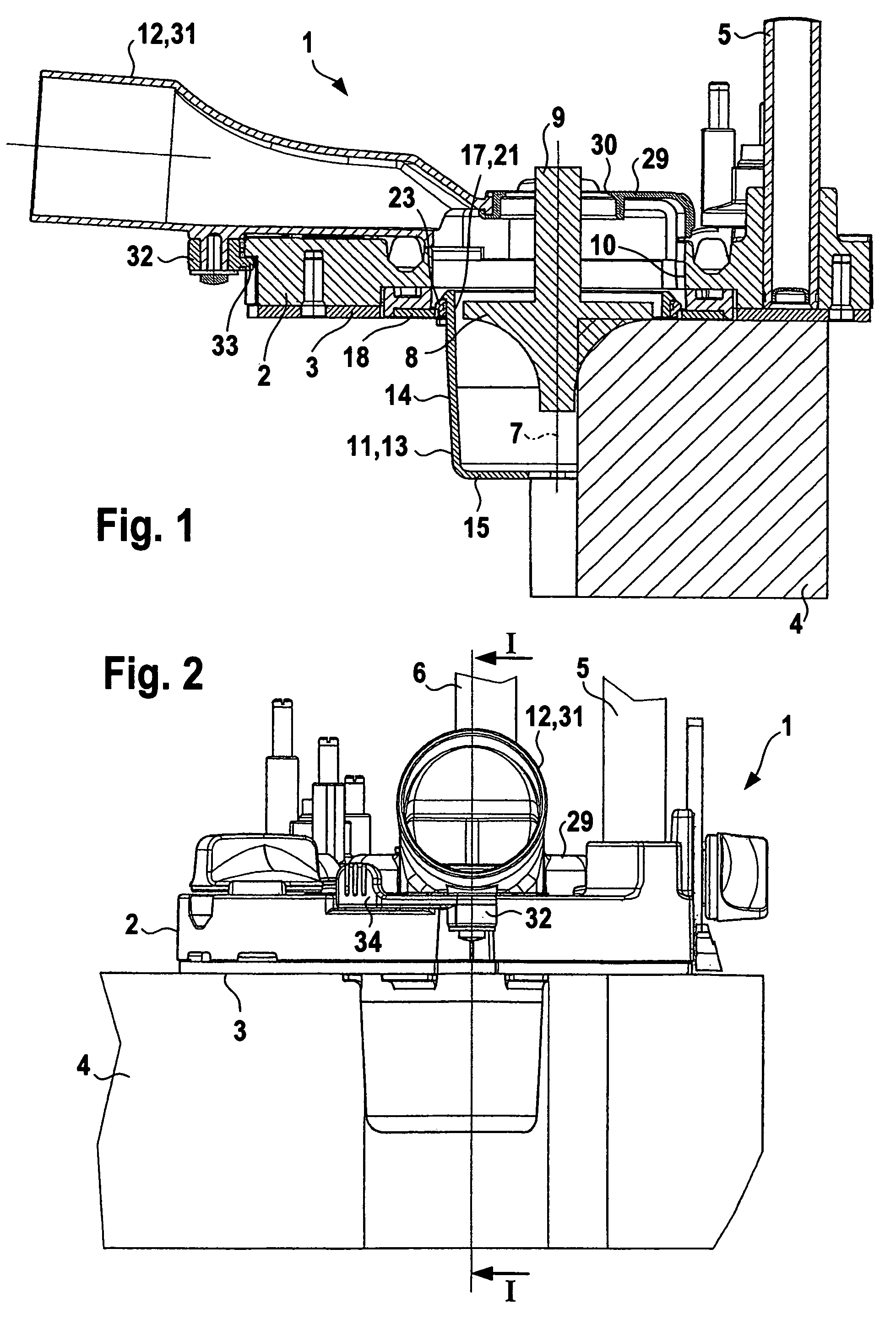
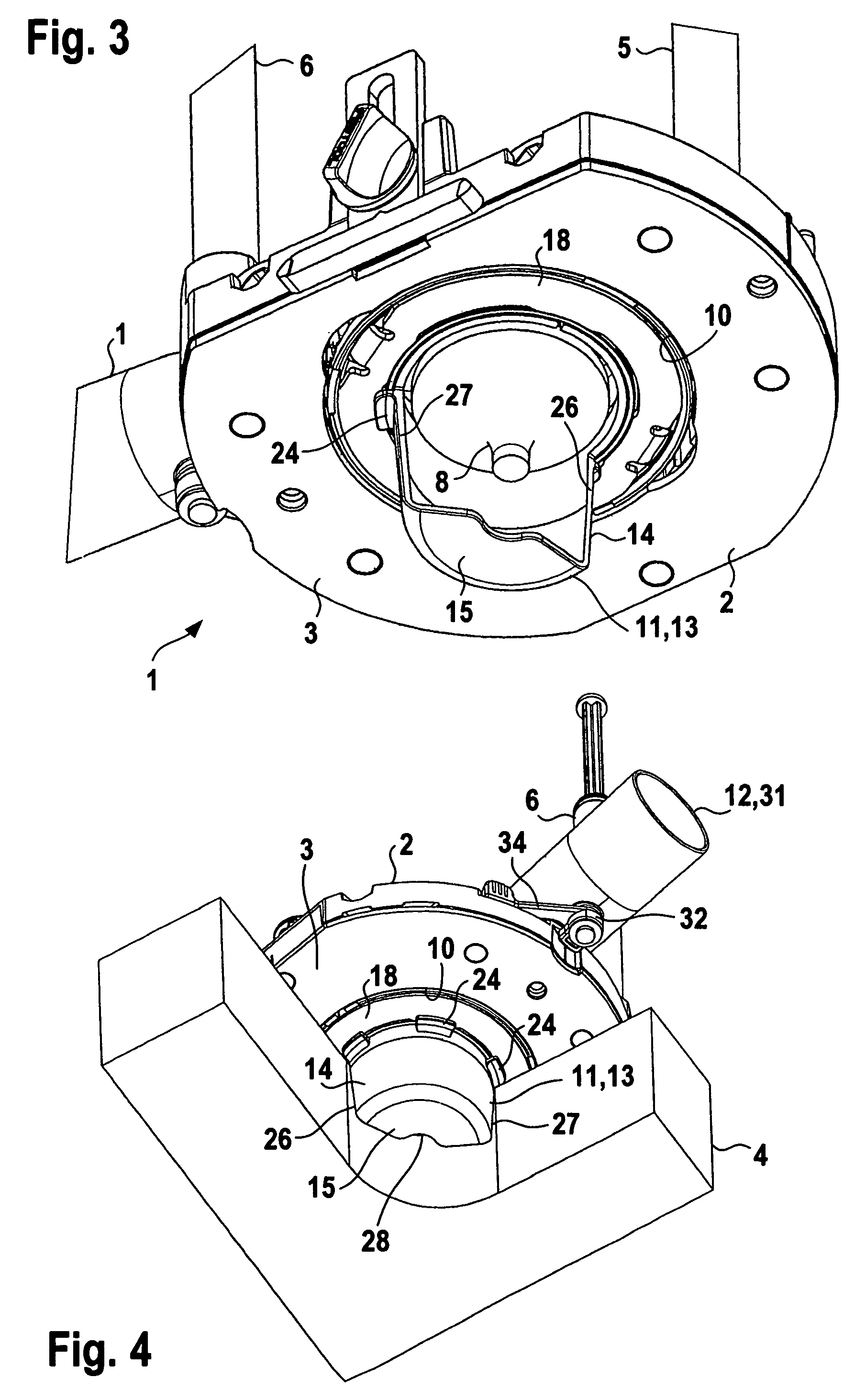
[0020]A router has a table unit 1 with a foot plate 2, whose bottom side 3 is held engaged on a workpiece 4 to be routed. Two support columns 5 and 6, which are spaced apart, extend upward from the foot plate, to carry a drive unit, not illustrated able to be moved along the support columns 5 and 6. The drive unit comprises a drive motor, a transmission and a chuck for a routing tool 8 extending in an axial direction 7 (which is parallel to the support columns 5 and 6), the shank of the routing tool 8 being secured in the chuck so that it is connected with the output shaft of the drive unit and in operation the routing tool 8 performs a rotary movement about the axis 7. The routing tool 8 is represented in FIG. 1 without the chuck of the drive unit. The routing tool 8 extends through the central access opening 10 in the foot plate 2 and may be shifted into a position projecting downward from the foot plate 2 by sliding the drive unit along the support columns 5 and 6, in which posit...


PUM

PropertyMeasurementUnit
angleaaaaaaaaaa
angleaaaaaaaaaa
angleaaaaaaaaaa

Abstract

A dust extractor device of a router has rotatable dust trap part able to be connected with a foot plate of the router and arranged to the side of the routing tool underneath the foot plate, such dust trap part being open toward the routing tool. The foot plate has an access opening for the routing tool. The dust trap part is constituted by an extractor hood with a hood casing at least essentially centered on the axis of rotation and a hood floor. The hood casing and the hood floor extend in the peripheral direction through an angle equal to or less than 180°. The extractor hood is open at its top side and opens into the access opening. The top end region of the extractor hood is rotatably supported on a holder, which is detachably secured to the foot plate and in the position of use extends around the access opening. The top side of the access opening is provided with a covering means, which is detachably attached to the foot plate and covers the access opening, such covering means having in it an access opening for the routing tool. The connection means is, in the position of use, in open connection with the access opening.

Description

BACKGROUND OF THE INVENTION[0001]The invention relates to a dust extractor device for a router in the case of which the router possesses a foot plate, to be placed on the work to be routed, having an access opening for the passage of a routing tool, such tool being adapted to be connected with the drive shaft of a router drive unit arranged in a vertically adjustable fashion above the foot plate and able to be caused to perform a rotary movement, comprising a dust trap part adapted to be releaseably secured to the foot plate, such dust trap part being arranged to the side of the routing tool in its position of use and being open toward the routing tool able to be turned about the axis of rotation so that during operation the router dust or the like entering the dust trap part is aspirated into an extractor connection means.THE PRIOR ART[0002]In the case of a dust extractor device disclosed in the German patent publication 20,216,066.1 (utility model) the dust trap part has a funnel-...

Claims


Application Information

Patent Timeline
Patent Type & Authority Patents(United States)
IPC IPC(8): B23C1/20B23Q11/00B27C5/10
CPCB23Q11/0046B27C5/10Y10T409/304088Y10T409/306608
Inventor STEIMEL, JOHANNESMANZ, BERNHARDSTARK, MARKUSHOLTZ, ARNE
Owner FESTOOL GMBH
Why Eureka
Try Eureka