Safety needle and catheter assembly

a safety needle and catheter technology, applied in the direction of guide needles, needles, catheters, etc., can solve the problems of putting other health care workers at risk as well, and putting others outside the hospital

Inactive Publication Date: 2007-11-06
SMITHS MEDICAL ASD INC
View PDF18 Cites 84 Cited by
  • Summary
  • Abstract
  • Description
  • Claims
  • Application Information

AI Technical Summary

Problems solved by technology

It is at this juncture that the exposed needle tip creates a danger of an accidental needle stick occurring which leaves the health care worker vulnerable to the transmission of various, dangerous blood-borne pathogens such as human immune virus (HIV) and hepatitis.
Careless disposal of used needles can put other health care workers at risk as well.
Even others outside the health care profession, for example those involved in the clean-up and final disposal of medical waste, are at risk of an accidental needle stick from a carelessly discarded needle.
One of the drawbacks to this design is the amount of friction force exerted against the needle by the split flange.
A tight fit of the flange against the catheter wall causes great friction against the needle making it difficult to be withdrawn from the catheter by the clinician.
A lose fit leaves the flange prone to releasing prematurely from the catheter as the needle is withdrawn, creating the potential that the needle tip will be left exposed.
A potential issue with this design develops when the needle guard is not properly seated into the. catheter hub.
If the distal end of the needle guard arm is not in alignment with the groove in the catheter hub, excessive forces are placed on the needle causing a high drag force as the clinician removes the needle.
And, since the needle guard arm is not properly seated in the groove, it may prematurely release from the catheter hub upon the removal of the needle leaving the needle tip exposed.
The prior art safety catheters all exhibit one or more drawbacks that have thus far limited their usefulness and full acceptance by health-care workers.

Method used


Image

  • Safety needle and catheter assembly
  • Safety needle and catheter assembly
  • Safety needle and catheter assembly

Examples


Embodiment Construction

[0020]As used herein, the term “proximal” refers to a location on the catheter and needle assembly with needle tip protector closest to the clinician using the device and thus furthest from the patient on which the device is used. Conversely, the term “distal” refers to a location farthest from the clinician and closest to the patient.

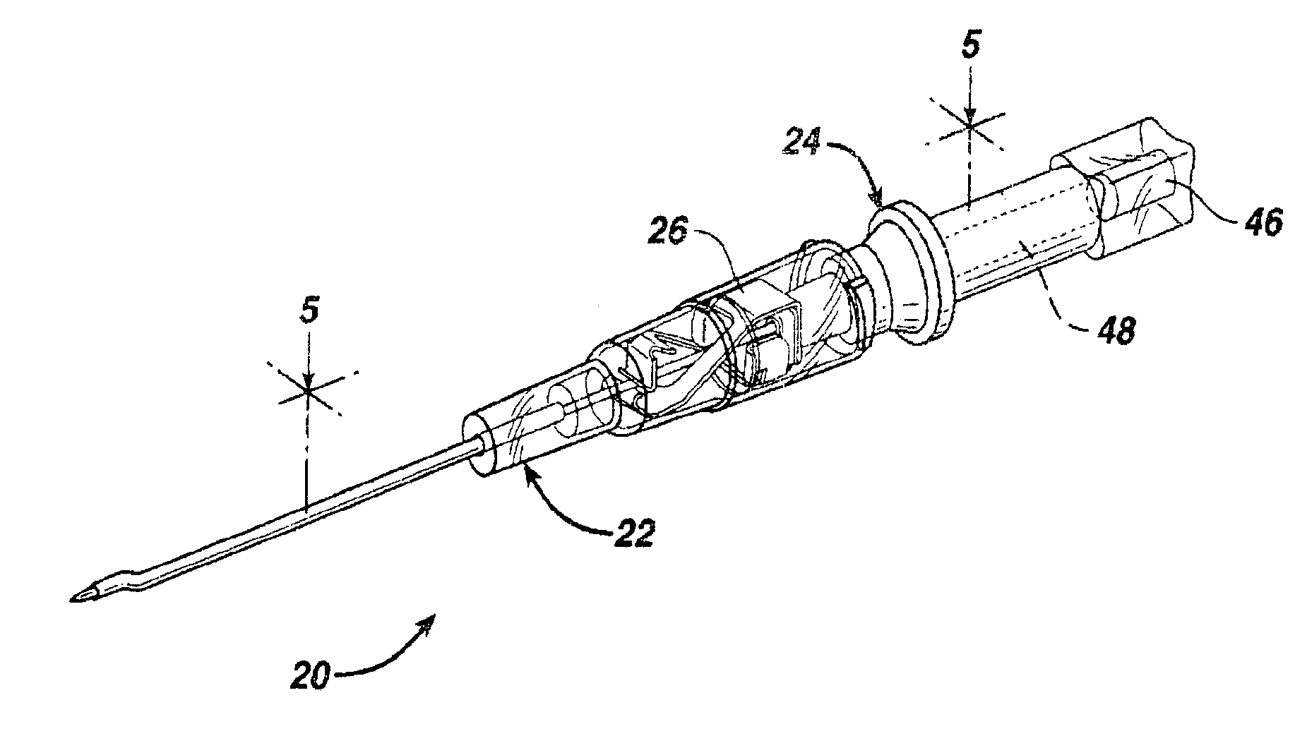
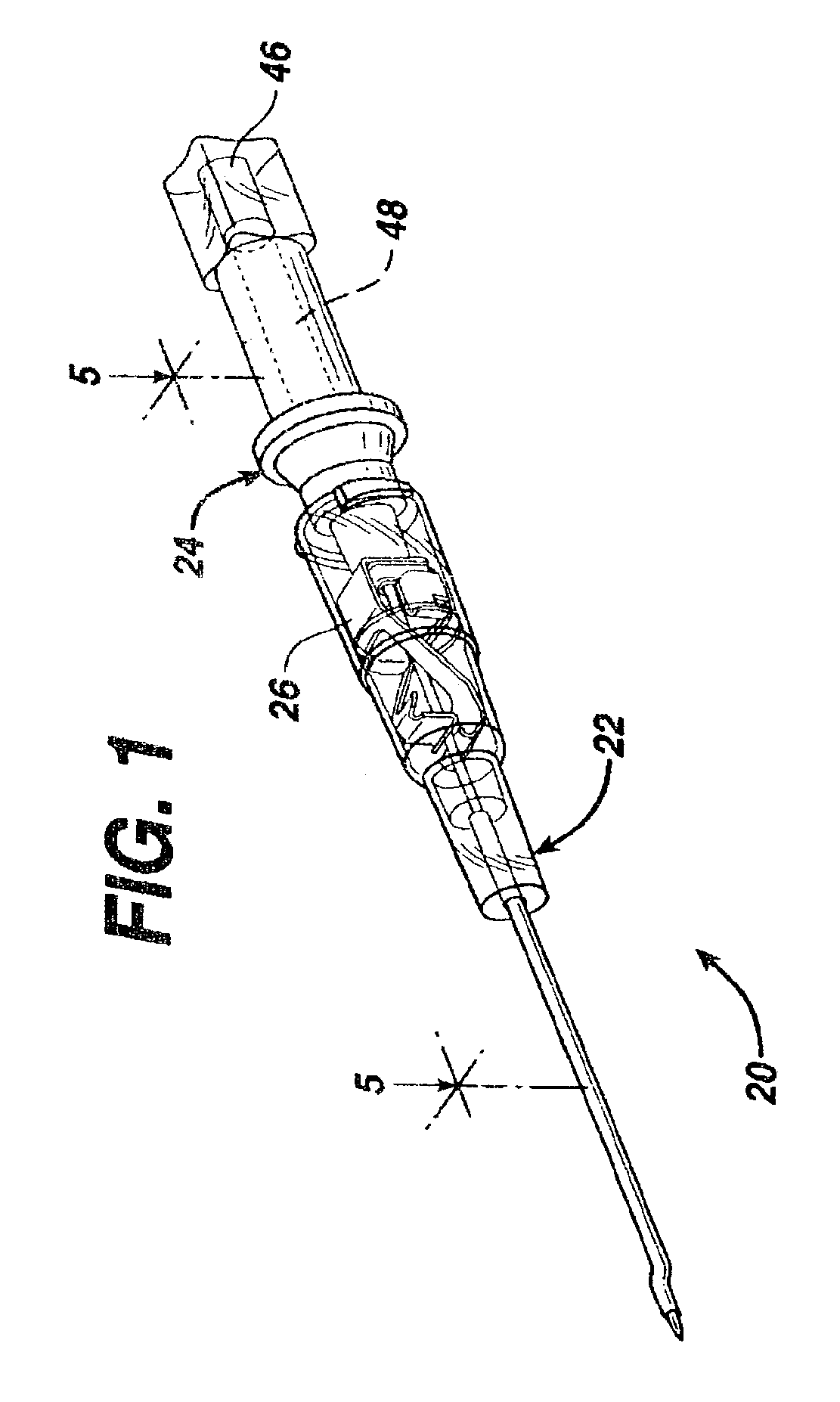
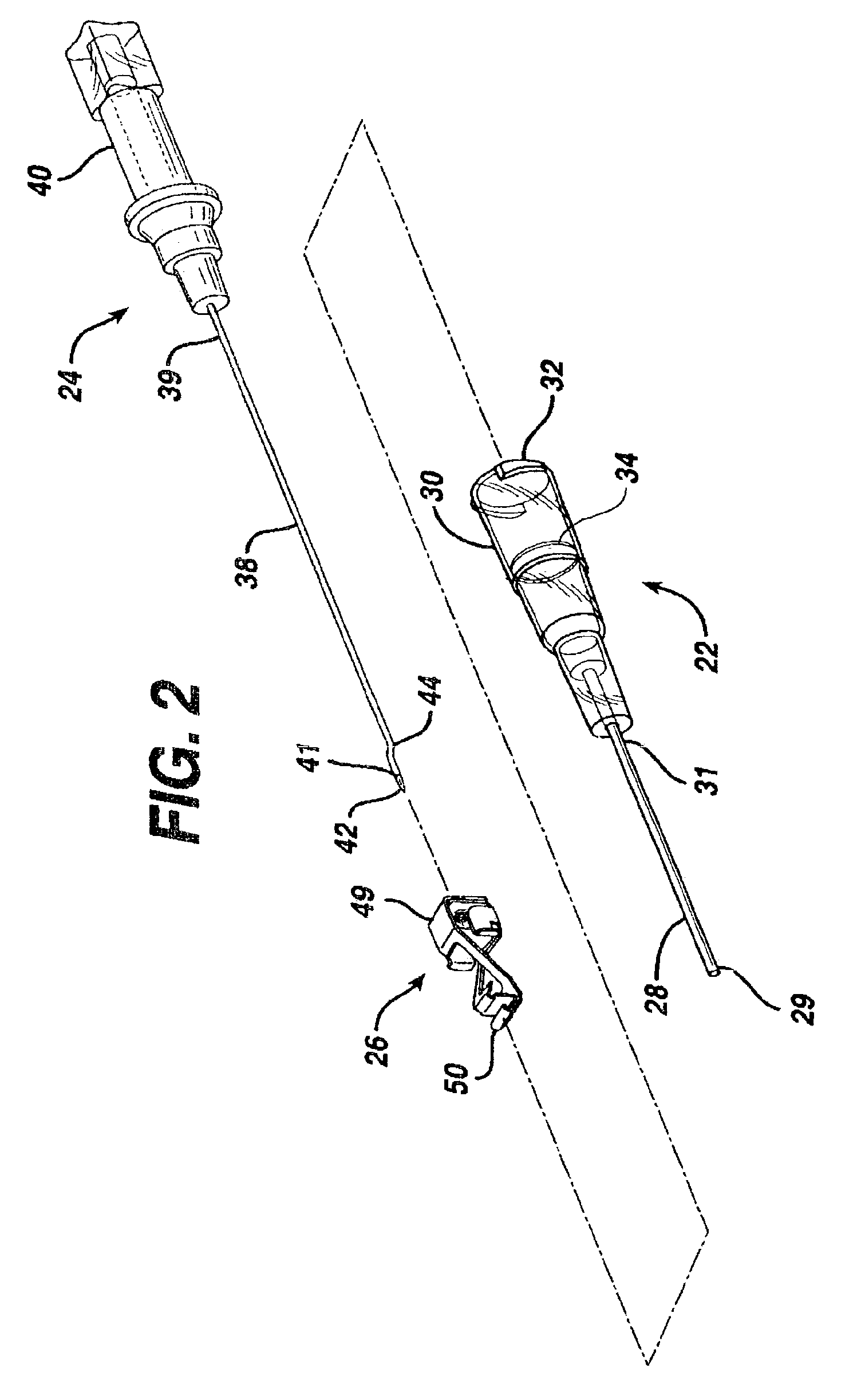
[0021]As illustrated in FIGS. 1 and 2, IV catheter assembly 20 comprises catheter assembly 22 and needle assembly 24. Needle assembly 24 further includes needle tip protector 26. Catheter assembly 22 includes catheter 28 which is a tubular structure having a proximal end 31 and distal end 29. Proximal end 31 of catheter 28 is fixedly attached to catheter hub 30. Catheters are well known in the medical art and one of many suitable materials, most of which are flexible thermoplastics, may be selected for use in catheter 28. Such materials may include, for example, polyurethane or fluorinated ethylene propylene. Catheter hub 30 is a generally tubular stru...


PUM


Abstract

A catheter and introducer needle assembly having a needle with a proximal and distal end attached to a needle hub and a bent area therebetween. The device further includes a tubular catheter having proximal and distal ends in which the introducer needle can be coaxially received within the catheter. The device has a hollow catheter hub having a distal end attached to the proximal end of the catheter and is in fluid communication therewith. The assembly includes a needle tip protector having a proximal end and a distal end disposed within the catheter hub. The distal end of the protector covers the needle tip when the needle is removed from the catheter. The protector has a proximal opening at its proximal end wherein the bent area is angled away from the proximal opening such that when the needle is removed from the catheter the protector remains attached to the needle.

Description

FIELD OF THE INVENTION [0001]The present invention relates, in general, to intravenous (IV) catheters and, more particularly, to a safety IV catheter with a needle tip protector that will automatically cover the needle tip upon needle withdrawal.BACKGROUND OF THE INVENTION [0002]An intravenous (IV) catheter is an instrument that is used to introduce certain fluids such as saline solution directly into the bloodstream of a patient. Typically, a needle or other stylet is first introduced through the cannula portion of the catheter and into the skin of the patient at the desired location such as the back of the patient's hand or a vessel on the inside of the arm. Once insertion is complete, the needle is removed from the cannula portion of the catheter. After removing the needle, a fluid handling device such as a syringe is attached to the luer fitting located at the proximal end of the catheter hub. Fluid then flows directly from the fluid handling device through the catheter into the...

Claims


Application Information

Patent Timeline
Patent Type & Authority Patents(United States)
IPC IPC(8): A61M5/178A61M5/32A61M25/06
CPCA61M25/0618A61M5/3273A61M2005/325
Inventor MCGURK, JOSEPH P.
Owner SMITHS MEDICAL ASD INC
Why Eureka
Try Eureka