System for withdrawing body fluid

a body fluid and system technology, applied in the field of system for withdrawing body fluid, can solve the problems of patient's death, long-term side effects, major scarring on the sensitive finger tips, etc., and achieve the effects of less curved, easy adaptation, and increased internal pressur

Inactive Publication Date: 2007-11-06
ROCHE DIABETES CARE INC
View PDF19 Cites 193 Cited by
  • Summary
  • Abstract
  • Description
  • Claims
  • Application Information

AI Technical Summary

Benefits of technology

[0018]The system according to the invention can be used particularly advantageously to obtain capillary blood from the finger pad. In addition it is also possible to withdraw blood or interstitial fluid from other body parts such as the arm.
[0019]An essential element of the system is the compression unit which results in the body part being squeezed together not only in the direction of the primary applied pressure but also results in the applied pressure being at least partially diverted such that a squeezing occurs with components of force transverse to the primary direction of pressure-application. As a result the region of the body part from which the withdrawal is to take place is pressed together laterally. The mode of action of this advantageous compression is elucidated later on the basis of the embodiments. The compression unit produces an increase of the internal pressure in a region of the body part. This region of increased internal pressure is adjacent to the region on which the applied pressure acts, or is surrounded by the region of applied pressure. A perforation device can now be used to perforate the region of increased internal pressure and remove body fluid.
[0020]The compression unit comprises a pressure-application region made of deformable material. On the one hand such a material makes the withdrawal process more pleasant for the user and, on the other hand, it also enables an easier adaptation to the various shapes and sizes of the body parts. Deformable plastics such as elastomers, rubbers and such like can for example be used as materials for the pressure-application region. The pressure-application region is preferably ring-shaped.
[0021]This represents a technically significant difference to the device described in FIGS. 15 to 16 of U.S. Pat. No. 5,951,493. In the device of the prior art an arrangement of separate lever arms is used to laterally press together the body surface. This has a number of disadvantages. As a result of the distance between the lever arms, the lateral squeezing of the skin surface is incomplete since areas remain untouched between the lever arms. Furthermore in the worst case the skin can get stuck between the lever arm while they move together. Finally it should be noted that the device of the prior art is neither designed nor suitable for fitting snugly to body surfaces of various sizes and shapes. The device is primarily intended to withdraw body fluid from a region of the arm which is less curved compared to the finger pad. The said problems can be avoided by using a pressure-application region made of a deformable material which preferably has a ring shape.
[0022]The system for removing body fluid additionally has a perforation device to produce a body opening. Such a perforation device can be a lancet or needle.
[0023]In the case of a lancet it is preferably completely removed from the tissue after the incision such that body fluid emerging from the site of incision is accessible. In the case of a needle it can remain at the maximum puncture depth in order to extract body fluid from this depth or it can be withdrawn until it reaches the skin surface in order to take up liquid from this position.

Problems solved by technology

In the case of a hypoglycaemia the patient can fall into a coma and even die since the brain is no longer adequately supplied with glucose.
In contrast hyperglycaemic states can lead to long-term side-effects such as blindness, gangrenes and such like.
This operation which is frequently referred to as “milking” by diabetics can hitherto only be avoided when the puncture is very deep and correspondingly unpleasant for the patient and can lead to major scarring on the sensitive finger tips.
Devices known in the prior art attempt to stimulate the outflow of blood by applying a vacuum but this has proven to be not efficient.
Only small amounts of fluid can be obtained with the device that are not adequate for commercial analytical systems.
The amounts of body fluid that can be obtained with this device are small and thus inadequate for conventional analytical systems.
A disadvantage of this device is that the needles for the withdrawal remain in the body and that in this state the finger support is moved.
This results in the movement of the needles in the finger which usually leads to considerable pain.
In addition it is extremely unlikely that blood will emerge while there is a needle in the finger so that the channel is closed by the needle.
However, due to the shape of the pressure-application region which widens conically towards the finger there is no conversion of a primary pressure-application movement into a lateral movement which squeezes the sampling region together.
As a result of the distance between the lever arms, the lateral squeezing of the skin surface is incomplete since areas remain untouched between the lever arms.
Furthermore in the worst case the skin can get stuck between the lever arm while they move together.
Finally it should be noted that the device of the prior art is neither designed nor suitable for fitting snugly to body surfaces of various sizes and shapes.
2 N. If greater compressive forces are used there is a danger that body fluid in the region of the increased internal pressure will be pressed out of this region.

Method used


Image

  • System for withdrawing body fluid
  • System for withdrawing body fluid
  • System for withdrawing body fluid

Examples


Embodiment Construction

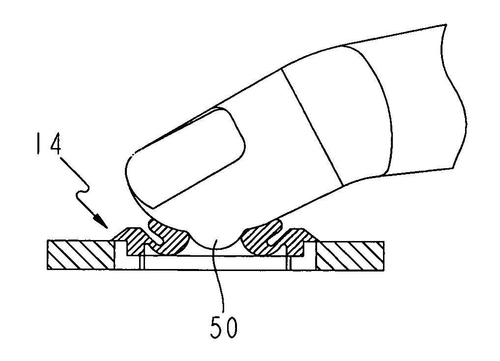
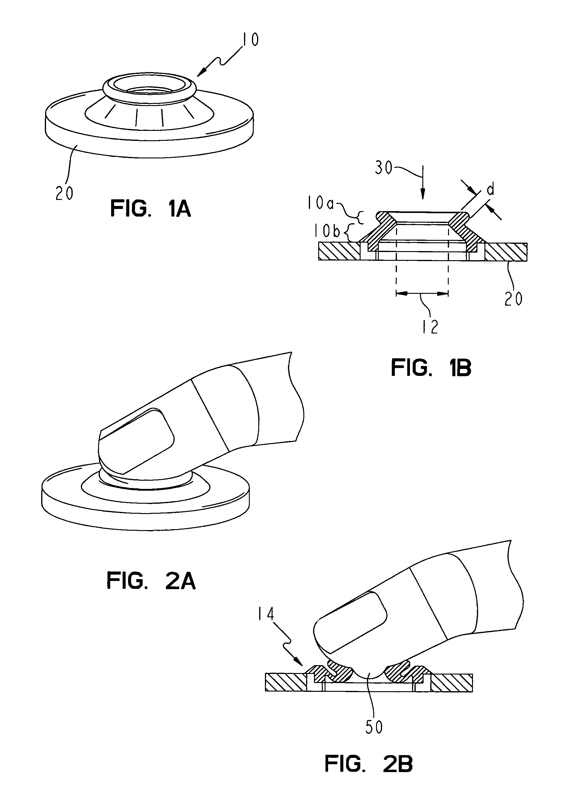
[0036]FIG. 1 shows a first embodiment of a deformable compression unit. FIG. 1A shows a perspective diagram of the compression unit (10) which is mounted on a plate (20). The cross-sectional diagram of FIG. 1B shows that the compression unit has two conically tapering regions (10a, 10b) which act as a pressure-application region. The upper pressure-application region (10a) narrows towards the plate (20) and the directly adjoining lower region (10b) widens towards the plate. The compression unit is constructed of a deformable plastic which is polyurethane in the example shown. Silicon and rubber can also be used. It is important that the compression unit can be deformed with sufficient ease as well as being adequately rigid in order to generate the necessary counter-pressure and an adequate pressure in the transverse direction. Suitable materials are in particular those with a hardness of less than 90 Shore preferably less than 50 Shore and particularly preferably in the range of 20 ...


PUM

PropertyMeasurementUnit
widthaaaaaaaaaa
inner widthaaaaaaaaaa
compressive forceaaaaaaaaaa

Abstract

System for withdrawing body fluid from a body part in particular the finger pad, comprising a compression unit that is deformed when the body part is pressed against it and increases the internal pressure in a region of the body part, and a withdrawal device. Deformation of the compression unit partially converts the primary pressing movement into a secondary movement which leads to an increase in the internal pressure in a region of the body part. The invention also comprises a system for stimulating the outflow of body fluid using a deformable compression unit.

Description

CROSS-REFERENCE TO RELATED APPLICATION[0001]This application is a continuation application of U.S. patent application Ser. No. 09 / 614,570 filed Jul. 12, 2000 now U.S. Pat. No. 6,589,260.BACKGROUND AND SUMMARY OF THE INVENTION[0002]The present invention concerns a system for withdrawing body fluid from a part of the body, especially the finger pad. Body fluids are primarily withdrawn for a subsequent analysis in order to diagnose diseases or to monitor the metabolic state of a patient. Such a withdrawal is carried out especially by diabetics in order to determine the blood sugar concentration. The aim of such a blood-sugar check that is usually carried out several times daily is to avoid hypoglycaemic states as well as hyperglycaemic states. In the case of a hypoglycaemia the patient can fall into a coma and even die since the brain is no longer adequately supplied with glucose. In contrast hyperglycaemic states can lead to long-term side-effects such as blindness, gangrenes and such...

Claims


Application Information

Patent Timeline
Patent Type & Authority Patents(United States)
IPC IPC(8): A61B17/14G01N33/48A61B5/15
CPCA61B5/1411A61B5/150022A61B5/150068A61B5/157A61B5/150519A61B5/15113A61B5/15186A61B5/150389A61B5/1405
Inventor SCHMELZEISEN-REDEKER, GUENTHERWEISS, THOMASDECK, FRANKEBERT, KLAUS PETER
Owner ROCHE DIABETES CARE INC
Why Eureka
Try Eureka