
Device for joining sheets of cardboard to form corrugated cardboard

a technology of corrugated cardboard and cardboard sheets, which is applied in the direction of presses, mechanical working/deformation, manufacturing tools, etc., can solve the problems of uneven gluing of the corrugated cardboard layers, inability to allow even pressure on the cardboard, and complicated cardboard structure, etc., to achieve the effect of small dimensions, accurate adjustment of work face width, and overall operating width of the devi

Active Publication Date: 2007-11-06
FOSBER
View PDF35 Cites 22 Cited by
  • Summary
  • Abstract
  • Description
  • Claims
  • Application Information

AI Technical Summary

Benefits of technology

This configuration enables precise adjustment of pressure profiles and reduces wear by adapting to cardboard width variations, ensuring even gluing and extending the device's operational flexibility and efficiency.

Problems solved by technology

The structure of the cardboard may also be more complex, when greater thickness is required.
This type of device had the serious drawback of not allowing even pressure on the cardboard, as the rollers do not adapt to the deformations of the underlying hot plates, which become deformed due to thermal dilations.
This results in uneven gluing of the layers of corrugated cardboard produced.
This type of solutions is particularly complex and costly, also as it is necessary to provide a high number of actuators.
Nonetheless, the solution offers limited advantages, as this device only allows to increase or decrease the active length of the device, that is the length along which there is pressure between the cardboard and underlying hot plates.
On the contrary, it is not possible to modulate and adjust the pressure profile.
When this occurs, there is greater wear on the pressure elements.
In this case, the edge areas of the belt (at the level of which there is no cardboard) rub directly on the hot plates and are subject to extremely high thermal stress.
In addition to the problem of wear, direct pressure contact between the belt and hot plates prevents normal lateral release of the humidity contained in the glue, with consequent difficulties in gluing.

Method used


Image

  • Device for joining sheets of cardboard to form corrugated cardboard
  • Device for joining sheets of cardboard to form corrugated cardboard
  • Device for joining sheets of cardboard to form corrugated cardboard

Examples


Embodiment Construction

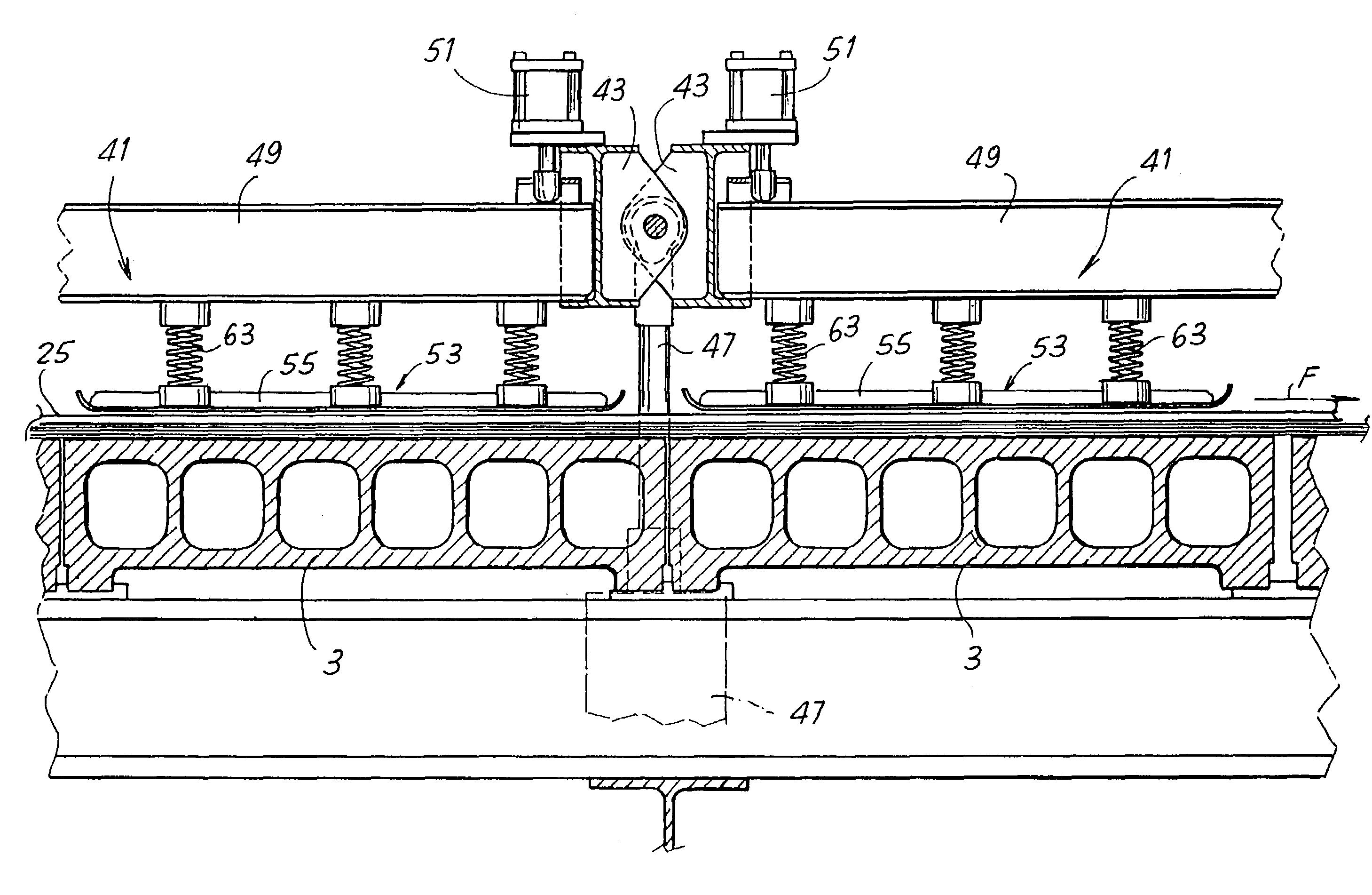
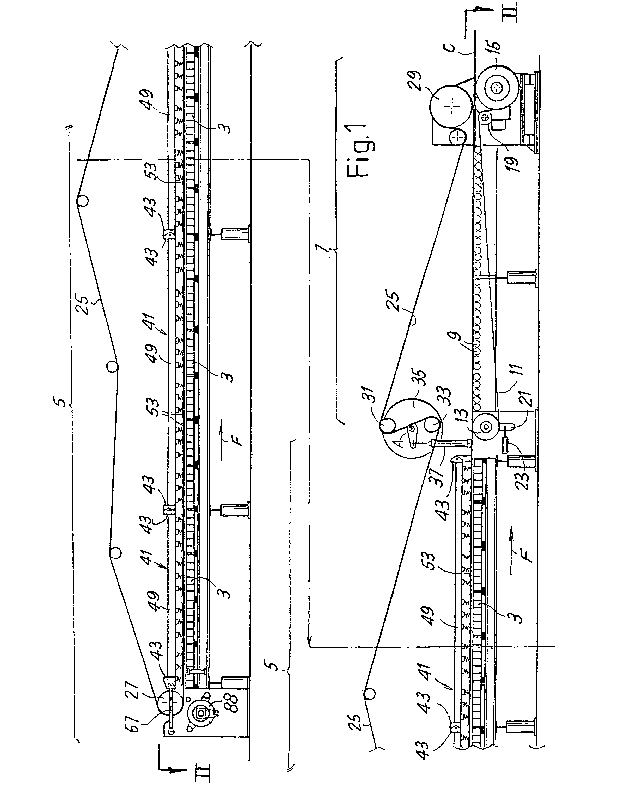
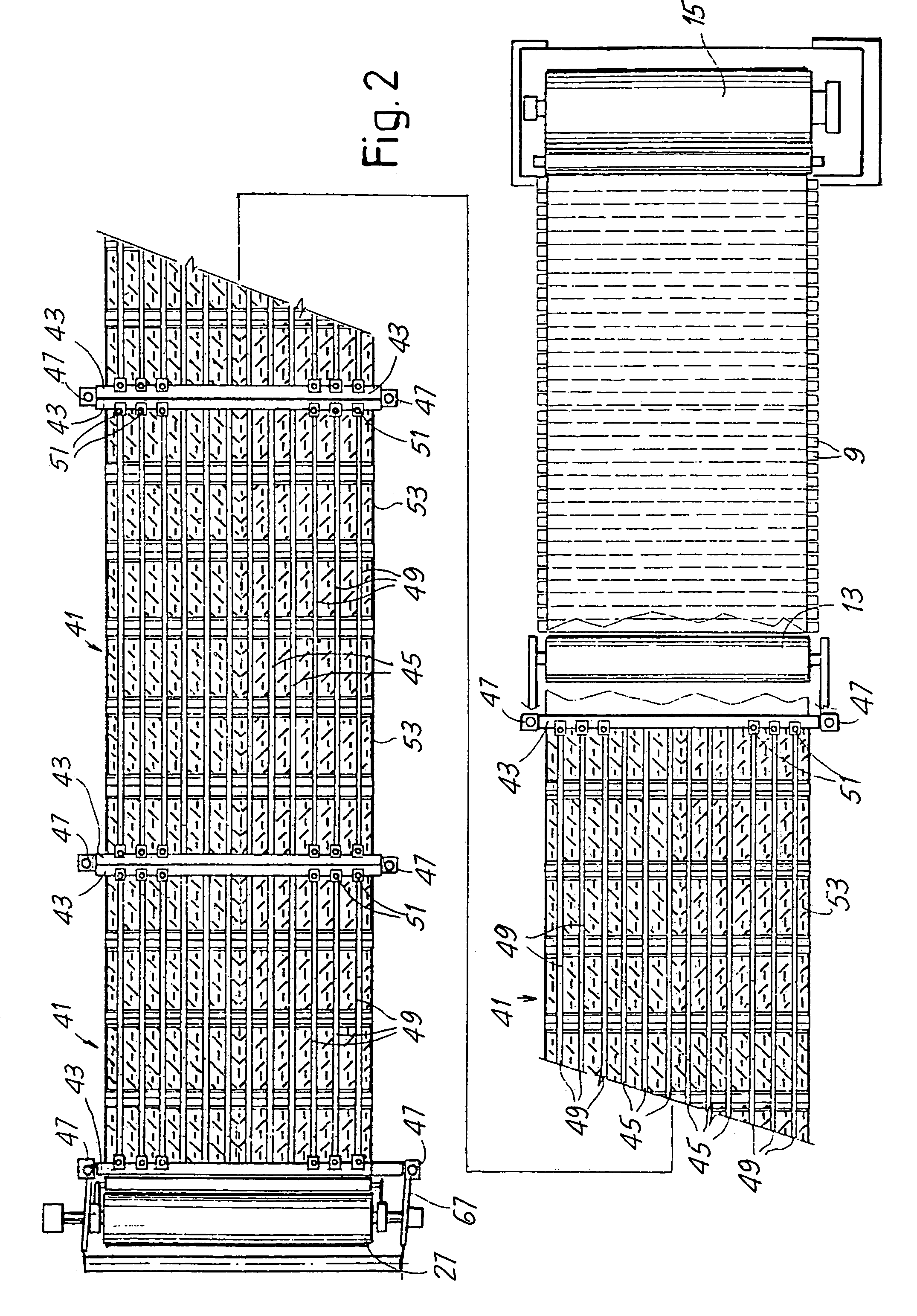
[0045]The device as a whole is represented schematically in FIGS. 1 and 2. In each of these figures the processing line is broken into two parts for representation requirements. It has a plurality of heated plates 3, aligned according to a longitudinal direction of cardboard feed, indicated with F. Each heated plate 3 extends transversely to the direction F for the entire useful width of the device. Downstream of the heated plates assembly 3, which form the hot section of the device, indicated with 5, is a conveying section 7, comprising a series of idle rollers 9 disposed more or less at the same level as the upper surface of the heated plates 3. The section 7 also comprises a conveyor belt 11 driven around rollers 13, 15, 19, at least one of which is motorized. The roller 13 is supported by an oscillating arm 21 acted upon by an actuator 23 to tighten the conveyor belt 11.

[0046]Extending above the sections 5 and 7 is a conveyor belt 25, driven around two drive rollers at the inlet...


PUM

PropertyMeasurementUnit
pressureaaaaaaaaaa
elasticaaaaaaaaaa
distanceaaaaaaaaaa

Abstract

The device to join a sheet of smooth cardboard (N4) to a sheet of corrugated cardboard (N1; N2; N3), comprises a series of heated plates (3) aligned according to a longitudinal direction of feed (F) of the cardboard and, above said heated plates, pressure elements (53) to press the cardboard against said heated plates, which are fastened by elastic elements to a supporting structure (41). The supporting structure comprises a plurality of frames (41) aligned according to the longitudinal direction (F) and the inclination of the frames is adjustable to modify the pressure profile applied by said pressure elements to the cardboard (C).

Description

TECHNICAL FIELD[0001]The present invention relates to a device to produce corrugated cardboard. In more detail, the present invention relates to so-called “double facer” device, used in the field of corrugated cardboard production to join by gluing a sheet of smooth cardboard to a sheet of corrugated cardboard, constituted by two or more layers.BACKGROUND OF THE INVENTION[0002]Corrugated cardboard is constituted by a multi-layer web product, constituted by at least a smooth layer joined by gluing to a corrugated layer. The smooth layer is usually called “liner”. Normally, the corrugated cardboard has at least two liners, between which and to which at least one corrugated layer is enclosed and glued. The structure of the cardboard may also be more complex, when greater thickness is required. For example, smooth and corrugated layers may be alternated. In this case, the two external layers are constituted by liners, that is they are smooth layers, between which corrugated layers separ...

Claims


Application Information

Patent Timeline
Patent Type & Authority Patents(United States)
IPC IPC(8): B30B15/34B31F1/28
CPCB31F1/2877
Inventor ADAMI, MAURO
Owner FOSBER
Learn More