Detection and suppression of electrical arcing

a technology of electrical arcing and detection and suppression, which is applied in the direction of emergency protective circuit arrangements, fault locations, instruments, etc., can solve the problems of increased risk of damage, damage to workpieces or chamber components, and increased risk of arcing with the duration of arcing, so as to eliminate abnormalities

Active Publication Date: 2007-11-06
APPLIED MATERIALS INC
View PDF9 Cites 49 Cited by
  • Summary
  • Abstract
  • Description
  • Claims
  • Application Information

AI Technical Summary

Benefits of technology

[0011]A third aspect of the invention is an apparatus and method of suppressing arcing without stopping the plasma process that is being performed in the plasma chamber. When arcing is detected, the power source briefly reduces its output power, preferably to zero power. Normally this will eliminate the arcing. After a very brief period of time, typically a few milliseconds or less, the power source increases its power output, preferably to its original value. If the arcing resumes, the power source reduces its power again for a brief period. Typically the arcing will completely disappear after a few repetitions of these brief periods of reduced power, so that the plasma process being performed in the chamber typically can resume after an interruption of only ten milliseconds or so.
[0015]When an abnormal change in the electrical impedance of the load is detected, the power source briefly reduces its output power, preferably to zero power. This may eliminate the abnormality. After a very brief period of time, typically a few milliseconds or less, the power source increases its power output, preferably to its original value. If the abnormality is detected again, the power source reduces its power again for a brief period. The abnormality may completely disappear after a few repetitions of these brief periods of reduced power, so that the normal operation of the power source can resume.

Problems solved by technology

If any electrical arcing occurs between the plasma and the workpiece being manufactured, or between the plasma any of the chamber components, damage may occur to the workpiece or the chamber components.
The risk of damage increases with the duration of the arcing.

Method used


Image

  • Detection and suppression of electrical arcing
  • Detection and suppression of electrical arcing
  • Detection and suppression of electrical arcing

Examples


Embodiment Construction

1. Hardware

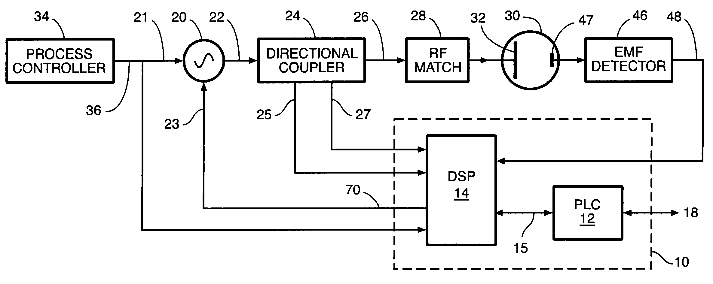
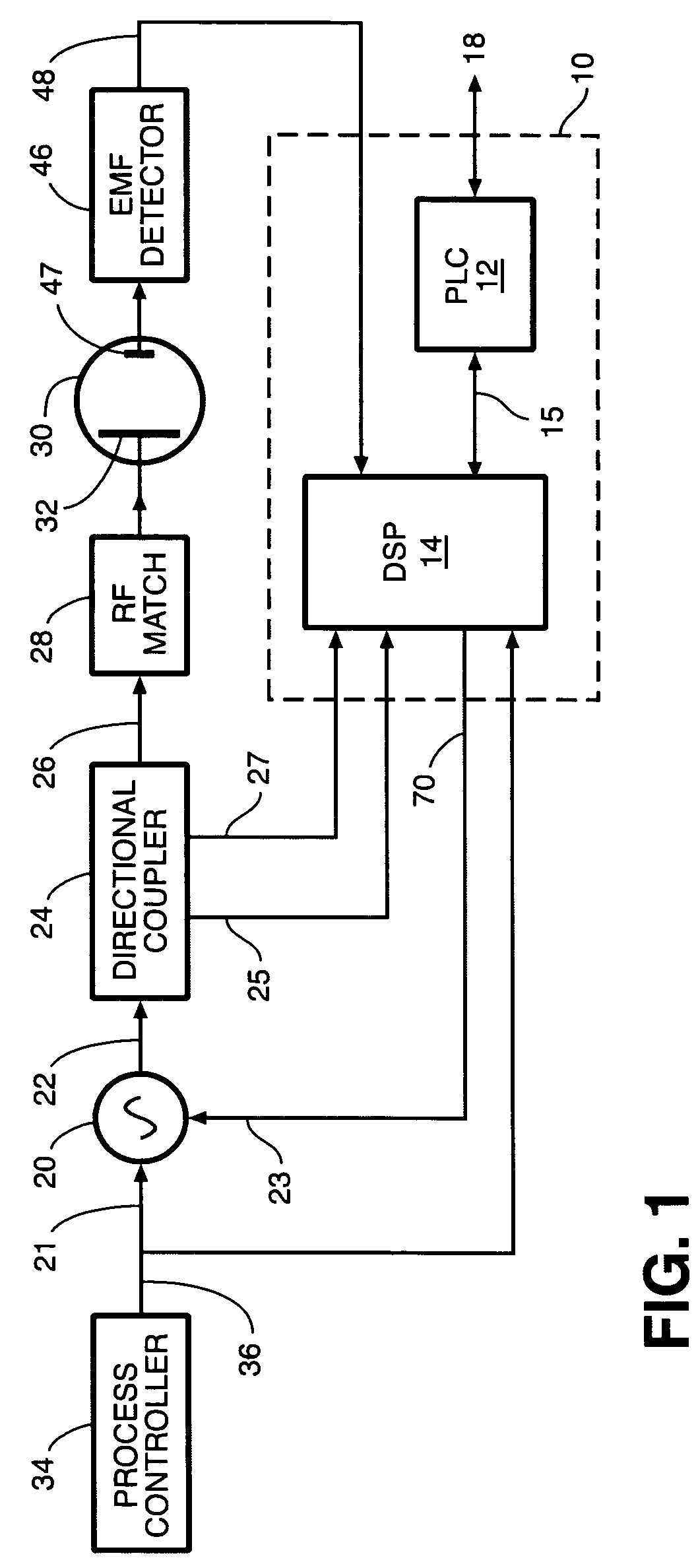
[0028]FIG. 1 shows an apparatus that can both detect arcing and suppress arcing according to different aspects of the present invention. The apparatus includes an electrical circuit 10 referred to herein as the “arc detection and suppression circuit” or “ADSC”. The ADSC 10 implements our novel arc detection and suppression algorithms as described below. The ADSC can be a digital circuit such as a programmable computer, an analog electrical circuit, or a combination of digital and analog circuits, examples of which are described below.

[0029]As stated in the above Summary of the Invention, our arc detection and suppression circuit also is useful more generally to detect or suppress abnormalities in impedance other than arcing. In this more general case, the ADSC 10 can be referred to as the “impedance abnormality detection and suppression circuit”. Suppression of an impedance abnormality means reversing the abnormal condition so as to return the impedance to its normal valu...


PUM

PropertyMeasurementUnit
timeaaaaaaaaaa
time periodaaaaaaaaaa
poweraaaaaaaaaa

Abstract

Method and apparatus for detecting or suppressing electrical arcing or other abnormal change in the electrical impedance of a load connected to a power source. Preferably the load is a plasma chamber used for manufacturing electronic components such as semiconductors and flat panel displays. Arcing is detected by monitoring one or more sensors. Each sensor either responds to a characteristic of the electrical power being supplied by an electrical power source to the plasma or is coupled to the plasma chamber so as to respond to an electromagnetic condition within the chamber. Arcing is suppressed by reducing the power output for a brief period. Then the power source increases its power output, preferably to its original value. If the arcing resumes, the power source repeats the steps of reducing and then restoring the power output.

Description

[0001]This application claims the benefit of U.S. Provisional Application No. 60 / 607,149 filed Sep. 4, 2004.FIELD OF THE INVENTION[0002]The invention relates generally to apparatus and methods for detecting or suppressing electrical arcing or any other abnormal change in the electrical impedance of a load to which a power source is supplying electrical power. Preferably the load is a plasma chamber used for manufacturing electronic components such as semiconductors and flat panel displays, and the abnormal change that the invention detects or suppresses comprises electrical arcing within the plasma chamber.BACKGROUND OF THE INVENTION[0003]Plasma chambers commonly are used for performing various processes such as chemical vapor deposition, sputter deposition and plasma-enhanced etching processes used in manufacturing an electronic workpiece such as a semiconductor device or flat panel display. Commonly the plasma within a plasma chamber is sustained by coupling RF or DC power from an...

Claims


Application Information

Patent Timeline
Patent Type & Authority Patents(United States)
IPC IPC(8): G01R31/08G01N27/66
CPCG01R31/1254G01R31/12H02H3/00
Inventor ANWAR, SUHAILMANACIO, REMEGIOPARK, CHUNG-HEEYIM, DONG-KILCHOI, SOO YOUNG
Owner APPLIED MATERIALS INC
Why Eureka
Try Eureka