Plate link chain having inner and outer plate members

Active Publication Date: 2007-11-13
AUMUND FORDERTECHN
View PDF7 Cites 2 Cited by
  • Summary
  • Abstract
  • Description
  • Claims
  • Application Information

AI Technical Summary

Benefits of technology

[0008]The invention has the advantage that the thickness of the material of the individual plates can be limited to a value that enables an economical manufacture without thereby limiting the permissible tensile load of the chain; rather, the tensile load of the chain can be increased while using two or more, in other words three or four or a number of individual plates that is advantageous in the technical design of the plate link chain for the respective formation of an inner plate member. Since only one individual plate is connected with the angle bracket, the manufacture of this individual plate is also facilitated, since the loading of the plate link chain by the further components of the conveying means mounted on the angle brackets is less than the tensile loading that exists in the chain. Thus, the inventively configured chain respectively has the best material utilization coefficients.
[0009]Pursuant to one embodiment of the invention, the angle bracket is monolithically formed with the individual plate that carries it, whereby the angle bracket is produced directly by bending, pressing, or some other appropriate manufacturing process. This embodiment has the special advantage that it is no longer necessary to deform the entire thickness of the corresponding plate of the chain, but rather that the app

Problems solved by technology

Such plate link chains have the problem that the maximum tensile load of the chain that can be taken up is determined by the weakest chain element, i.e. the inner plate member, the outer plate member, the sleeve or the link pin.
To the extent within the scope of the known manufacturing processes the plates are manufactured from rolled metal plate by stampin

Method used


Image

  • Plate link chain having inner and outer plate members
  • Plate link chain having inner and outer plate members

Examples


Example

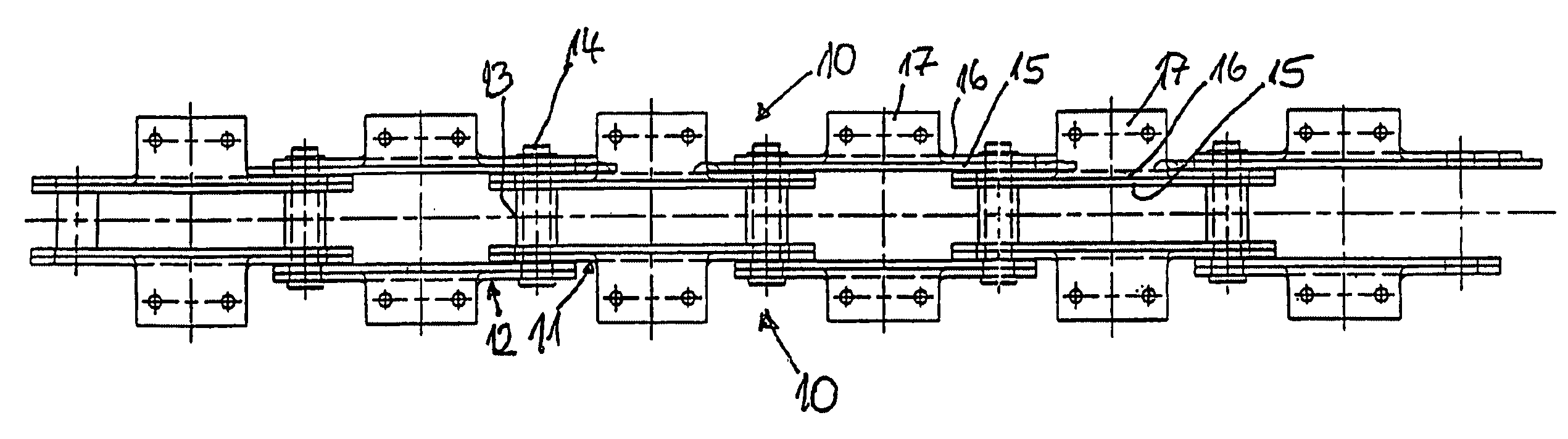
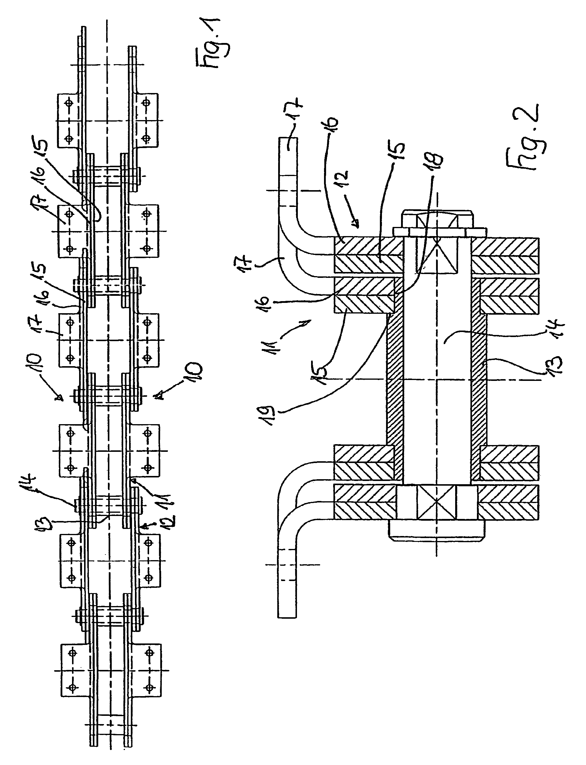
[0017]The plate link chain illustrated in FIG. 1 is comprised of two chain strands 10 that are disposed parallel to one another, whereby each chain strand 10 is formed of a sequence of inner plate members 11 and outer plate members 12. The oppositely disposed inner plate members 11 and outer plate members 12 of the two chain strands 10 are respectively interconnected by sleeves 13 that connect the inner plate members 11, and link pins 14 that are inserted into the sleeves 13 through associated openings of the outer plate members 12.

[0018]As already apparent from FIG. 1, the inner plate members 11 and outer plate members 12 of the two chain strands 10 are each uniformly comprised of two parallel individual plates that are disposed on the sleeves 13 or the link pins 14, whereby in each case an inner individual plate 15 and an outer individual plate 16 are provided; the outer individual plates 16 are monolithically formed with an angle bracket 17 for the mounting of further components ...


PUM


Abstract

A plate link chain in the form of a conveyor chain comprising at least two chain strands that are disposed parallel to one another and are comprised of a sequence of inner plate members and outer plate members, wherein the inner plate members are provided with openings for receiving at least one sleeve for connecting the inner plate members of oppositely disposed chain strands, wherein the outer plate members are provided with openings aligned with the openings of the inner plate members to receive a link pin that extends through the sleeve and is fixed on the outer plate members, and wherein the inner plate members are comprised of at least two individual plates, one of which, of at least the inner plate members of one chain strand, is provided with angle brackets for the mounting of further chain components.

Description

[0001]This specification for the instant application should be granted the priority date of Feb. 11, 2003, the filing date of the corresponding German Patent application 203 02 130.4 as well as the priority date of 17 Dec. 2003, the filing date of the corresponding International patent application PCT / EP2003 / 014412.BACKGROUND OF THE INVENTION[0002]The invention relates to a plate link chain in the form of a conveyor chain, especially for platform or apron conveyors, bucket conveyors, or similar conveying means, comprised of at least two chain strands that are disposed parallel to one another and are comprised of a sequence of inner plate members and outer plate members, whereby the inner plate members are provided with openings for receiving at least one sleeve for connecting the inner plate members of the oppositely disposed chain strands, and the outer plate members are provided with openings that are lined with the openings of the inner plate members in order to receive a link pi...

Claims


Application Information

Patent Timeline
IPC IPC(8): B65G17/38B65G17/42
CPCB65G17/38B65G17/42B65G2201/06F16G13/06
Inventor BURKHARD, POPPECK
Owner AUMUND FORDERTECHN
Why Eureka
Try Eureka