Power vise

Inactive Publication Date: 2007-11-13
HOOPER RONALD L
View PDF17 Cites 41 Cited by
  • Summary
  • Abstract
  • Description
  • Claims
  • Application Information

AI Technical Summary

Problems solved by technology

However, oftentimes a worker must assemble or manipulate multiple part assemblies, and it can be cumbersome to hold the various parts in precisely the proper relationship to one another while simultaneously attempting to manually close the jaws on the vise to secure the parts.

Method used


Image

  • Power vise
  • Power vise
  • Power vise

Examples


Embodiment Construction

[0019]The present invention comprises various embodiments of a power vise in which a power source is connected to at least one of the vise jaws to drive the vise jaw. The vise may be screw-actuated, as in the case of a bench vise or the like, or hydraulically actuated, as desired. Electric or hydraulic power may be used to drive the driven jaw of the vise, and a force limiting mechanism may be provided between the power source and the driven jaw of the vise.

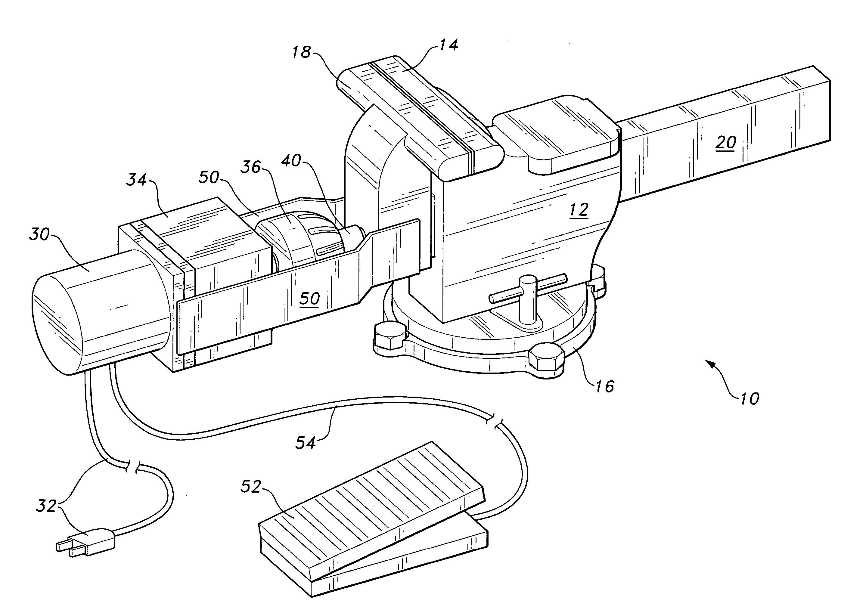
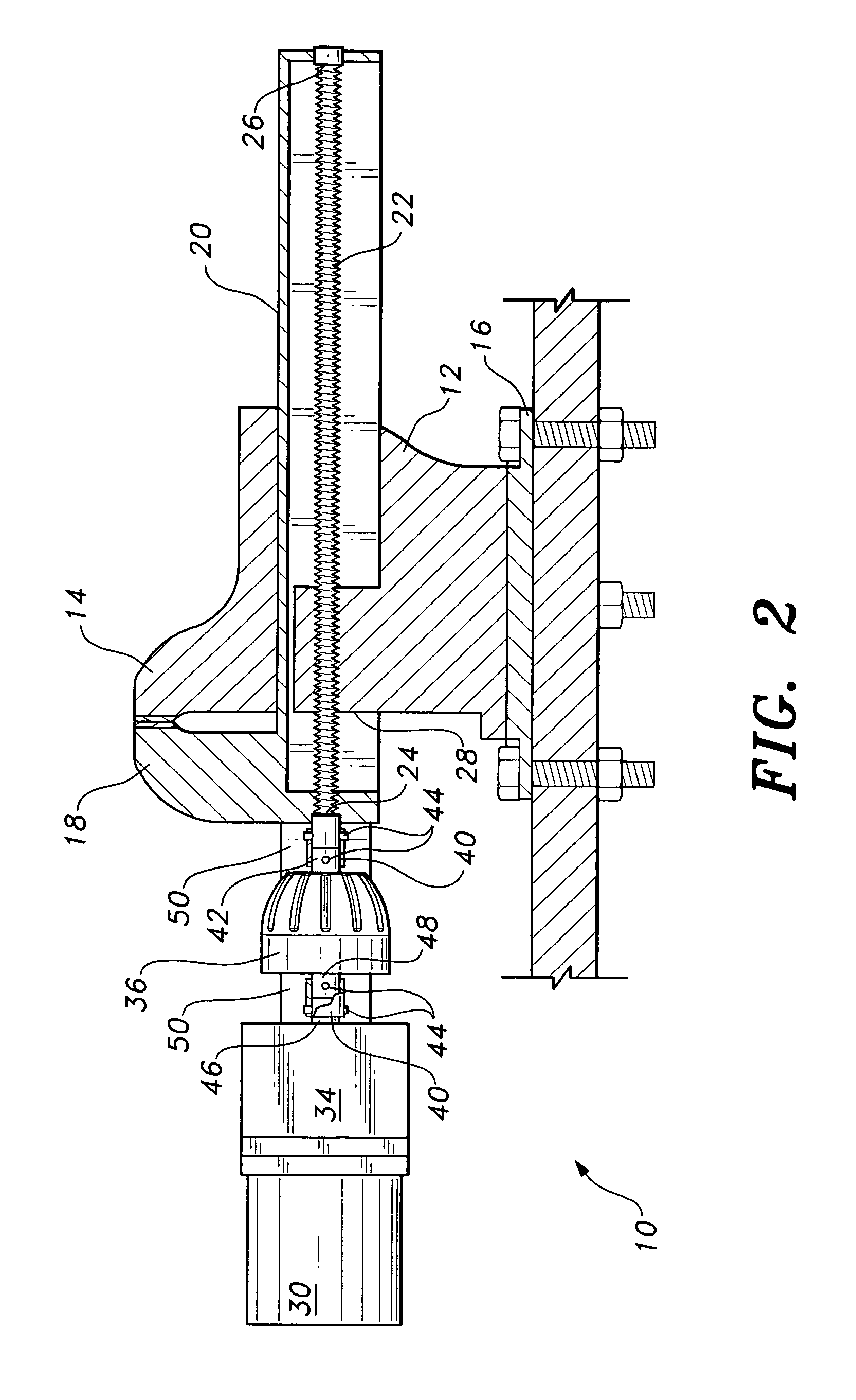
[0020]FIGS. 1 through 3 illustrate a first type of power-driven vise in accordance with the present invention, with FIGS. 1 and 2, respectively, providing perspective and elevation views in partial section of a first embodiment of the vise. The powered vise 10 of FIGS. 1 and 2 includes a vise body 12 having a fixed jaw 14 extending therefrom, as is conventional in bench vise and machinist's vise construction. The vise body 12 may be rotationally attached to a base 16 to allow the body 12 to be repositioned for convenience. The ba...


PUM


Abstract

A power vise in which a supplementary power source is used to open and close the jaws. The power vise may be actuated by a remote control, so the operator may have both hands free to hold the workpiece as it is placed in or removed from the vise and may also include a mechanism for regulating the pressure developed between the jaws. When the power source is electric, the electrically operated vise includes an output shaft of an electric motor connected to the advance screw of the vise to turn the screw and close or open the jaws. When the power source is hydraulic, the hydraulically operated vise includes a hydraulic ram, with a first jaw affixed to the hydraulic cylinder and a second jaw affixed to the piston rod of the hydraulic device. Hydraulic pressure is used to retract and extend the piston rod, thereby closing and opening the jaws.

Description

CROSS-REFERENCE TO RELATED APPLICATION[0001]This application claims the benefit of U.S. Provisional Patent Application Ser. No. 60 / 696,800, filed Jul. 7, 2005.BACKGROUND OF THE INVENTION[0002]1. Field of the Invention[0003]The present invention relates generally to vises and clamping tools used to temporarily hold a workpiece in place. More specifically, the present invention includes a power vise using either an electric motor or a hydraulic ram to move the jaws.[0004]2. Description of the Related Art[0005]Vises and similar clamping tools have been known and used for generations for temporarily holding a workpiece in place to allow a worker to use both hands in performing the necessary work. Generally, such devices are manually actuated, with no power being provided for the opening and closing of the jaws. The mechanical advantage provided by the advance screw pitch in a conventional vise is sufficient to provide more than adequate clamping pressure in virtually all circumstances, ...

Claims


Application Information

Patent Timeline
Patent Type & Authority Patents(United States)
IPC IPC(8): B25B5/00
CPCB25B1/103B25B1/18B25B1/16
Inventor HOOPER, RONALD L.
Owner HOOPER RONALD L
Why Eureka
Try Eureka