Shock-mitigating bolster

a technology of shock-mitigating bolsters and bolsters, which is applied in the direction of pedestrian/occupant safety arrangements, vehicle components, vehicle arrangements, etc., can solve the problems of accelerating and accelerating the force of craft and its occupants, causing the damage of personnel and equipment, and causing continued exposure to such forces

Active Publication Date: 2007-11-13
STIDD SYST
View PDF10 Cites 9 Cited by
  • Summary
  • Abstract
  • Description
  • Claims
  • Application Information

AI Technical Summary

Benefits of technology

[0007]In accordance with the foregoing and other objects and purposes, a personnel support device of the present invention is in the form of a bolster assembly which provides a support mechanism for a user when in a standing position as well as being capable of supporting a seat structure for a user in the sitting position. The bolster comprises a frame which is resiliently supported by a mounting plate through a shock-absorbing interface. A pair of pivot arms provides the primary connection between the frame and mount, allowing the bolster frame to rotate in a vertical arc with respect to the mount. The mounting plate is in turn rigidly affixed to the structure through which the shocks are transmitted, such as a vessel's deck or superstructure. The frame-mounting plate interface also includes the parallel combination of a damper and spring, the response characteristics of which may be adjustable to allow tuning of the response of the system in accordance with use requirements. The combination of the damper and spring absorb accelerations transmitted to the pivot arms, damping a large portion of the resultant force and providing attenuated, controlled motion of the bolster frame in connection therewith. The inventive construction provides an extremely reliable and durable shock-absorbing system, providing superior comfort and safety to a user, allowing fatigue-free long duration travel aboard high-performance craft subject to continued high-level shocks.

Problems solved by technology

Such speeds subject the craft and its occupants to tremendous shock accelerations and forces as the craft is buffeted by the seas.
Beyond the obvious difficulties that such forces create with respect to allowing the crew to perform their necessary duties, continued exposure to such forces can be hazardous and harmful to the craft's occupants.
The forces generated by such accelerations can be harmful to both personnel and equipment.

Method used


Image

  • Shock-mitigating bolster
  • Shock-mitigating bolster
  • Shock-mitigating bolster

Examples


Embodiment Construction

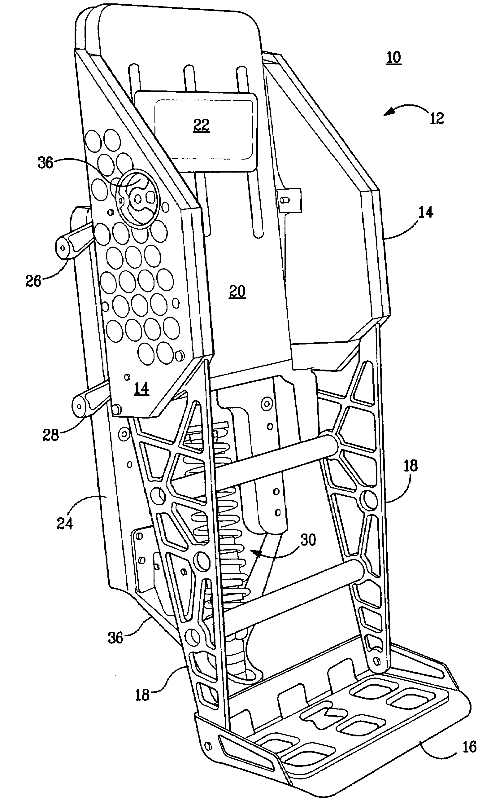
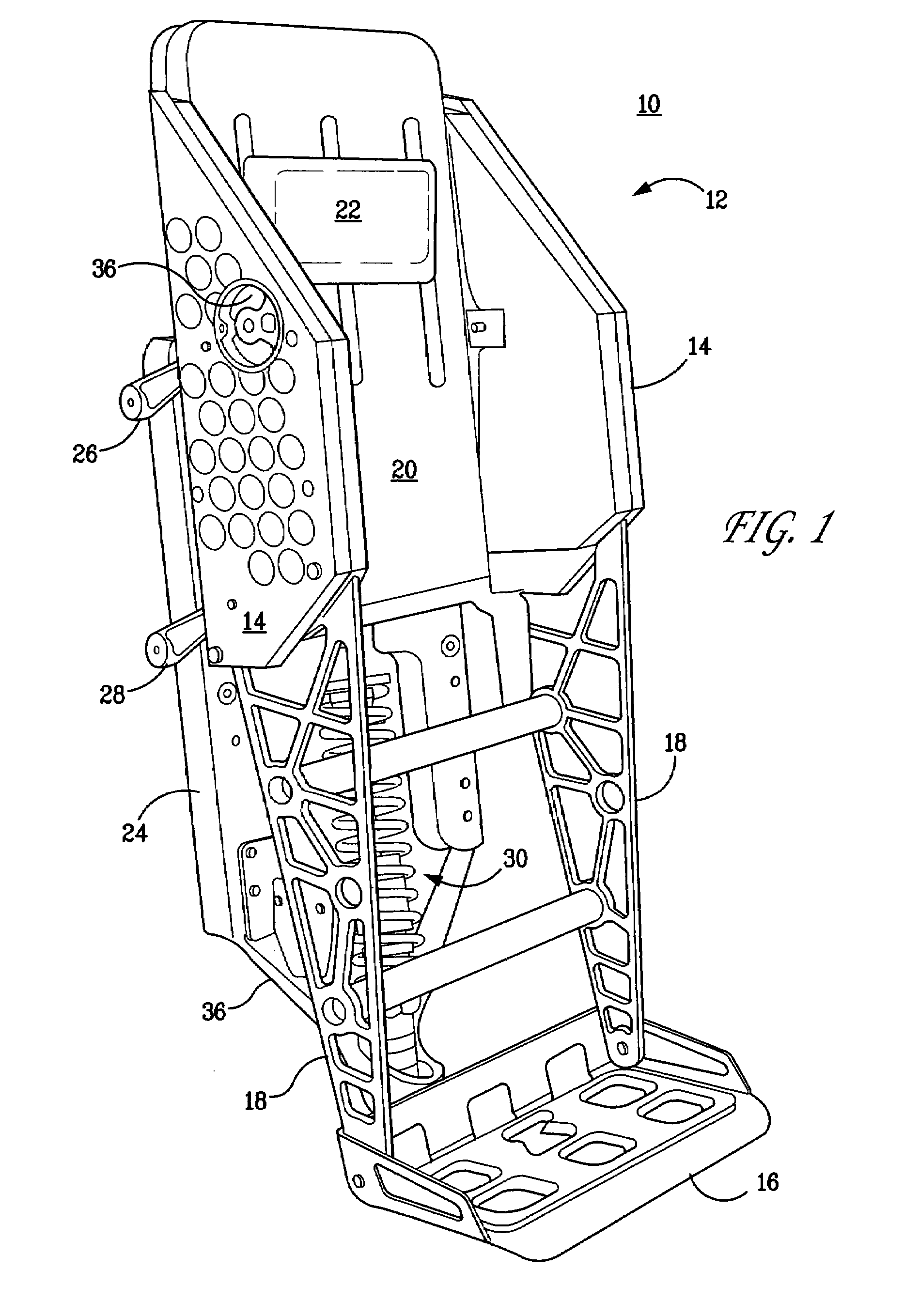
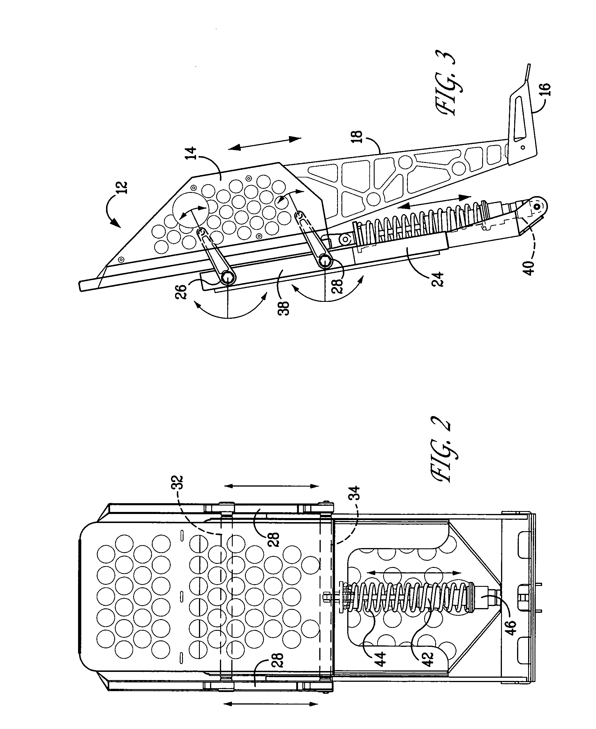
[0014]With initial reference to FIG. 1, shock-mitigating bolster device 10 depicts a unit configured to provide shock-absorption for a user in a standing position. Bolster frame 12 is of generally a U-shape construction, the user's torso being positioned between the side wings 14 of the frame. The user stands on footplate 16, which is mounted to frame side struts 18 joined to the bolster side wings. A lap belt (not shown) may be provided to retain the user within the confines of the bolster, while optional pivoting armrests (also not shown) may also be provided, and can be journaled in appropriate recesses 36 in the wings 14. The interior portion of the bolster frame is typically padded; the back cushioning 20 may be further provided with a vertically-adjustable lumbar support 22. The bolster frame is positioned and supported forwardly of back plate 24 by upper and lower pivot arm pairs 26, 28. Shock-absorber assembly 30 further connects the bolster frame with the back plate, and pr...


PUM


Abstract

A personal support device having particular utility for use by personnel in high-performance surface watercraft comprises a bolster adapted and dimensioned to support an occupant for shock isolation from accelerations experienced by the vessel. The bolster is mounted by pivot means extending between the bolster and a back plate which is rigidly mounted to the vessel. The pivot means permit the bolster to pivot in an arc with respect to the back plate. A shock absorber extends between the back plate and bolster to dampen the accelerations which would otherwise be passed to the bolster by the pivot means from the back plate. The bolster is capable of supporting a user in a standing position or receiving a seat assembly to allow an occupant to be seated.

Description

[0001]The present invention relates to a new and improved personal support system, and particularly to a bolster construction having superior shock-mitigating characteristics which can be of significant value for use by personnel in high-performance surface watercraft.BACKGROUND OF THE INVENTION[0002]High performance surface watercraft, such as employed by the military, are capable of sustained high-speed operation. Such speeds subject the craft and its occupants to tremendous shock accelerations and forces as the craft is buffeted by the seas. Beyond the obvious difficulties that such forces create with respect to allowing the crew to perform their necessary duties, continued exposure to such forces can be hazardous and harmful to the craft's occupants.[0003]The U.S. Navy MKU Special Operators Craft, for example, an 82 foot high-speed vessel, has a top speed of approximately 50 knots and a range of 500 nautical miles. It has a crew of 5 and is designed to carry up to 16 fully-equip...

Claims


Application Information

Patent Timeline
Patent Type & Authority Patents(United States)
IPC IPC(8): B60N2/42
CPCB60N2/503B60N2/505B63B29/04B60N2/544B60N2/507
Inventor MAROTTA, CHRISTOPHER J.DIGREGORIO, ROBERT
Owner STIDD SYST
Why Eureka
Try Eureka