Pump apparatus

a technology of pumping apparatus and pumping chamber, which is applied in the direction of positive displacement engine, piston pump, positive displacement liquid engine, etc., can solve the problems of high production cost, and achieve the effect of reducing cost and accurately dischargeing a constant amount of fluid

Active Publication Date: 2007-11-13
SMC CORP
View PDF22 Cites 28 Cited by
  • Summary
  • Abstract
  • Description
  • Claims
  • Application Information

AI Technical Summary

Benefits of technology

[0010]A general object of the present invention is to provide a pump apparatus which makes it possible to reduce the cost and which makes it possible to discharge a constant amount of a fluid highly accurately without causing any pulsation of the fluid even when the large amount of fluid flows in the pump.

Problems solved by technology

However the production cost becomes expensive, because the bellows is expensive.

Method used


Image

  • Pump apparatus
  • Pump apparatus
  • Pump apparatus

Examples


Embodiment Construction

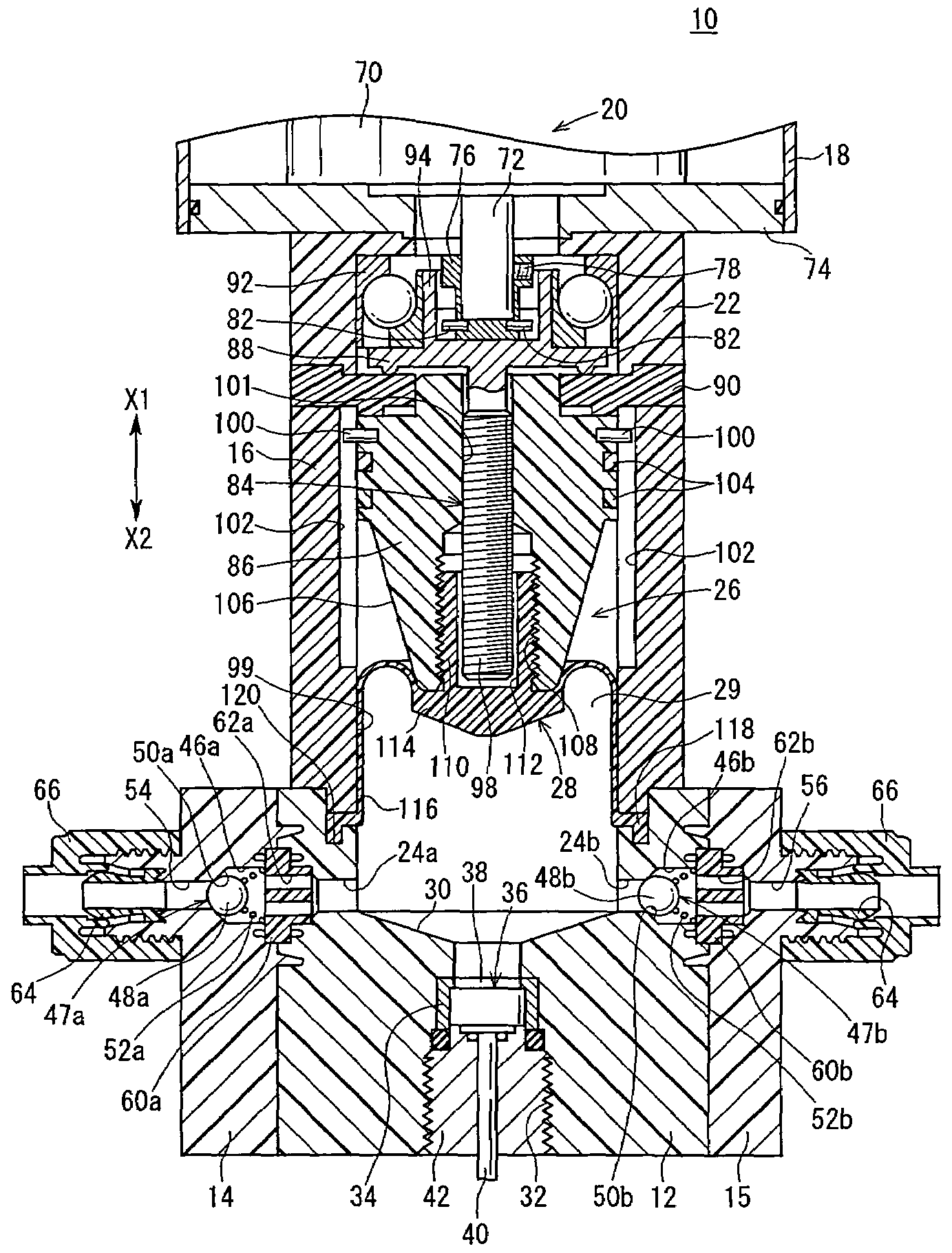
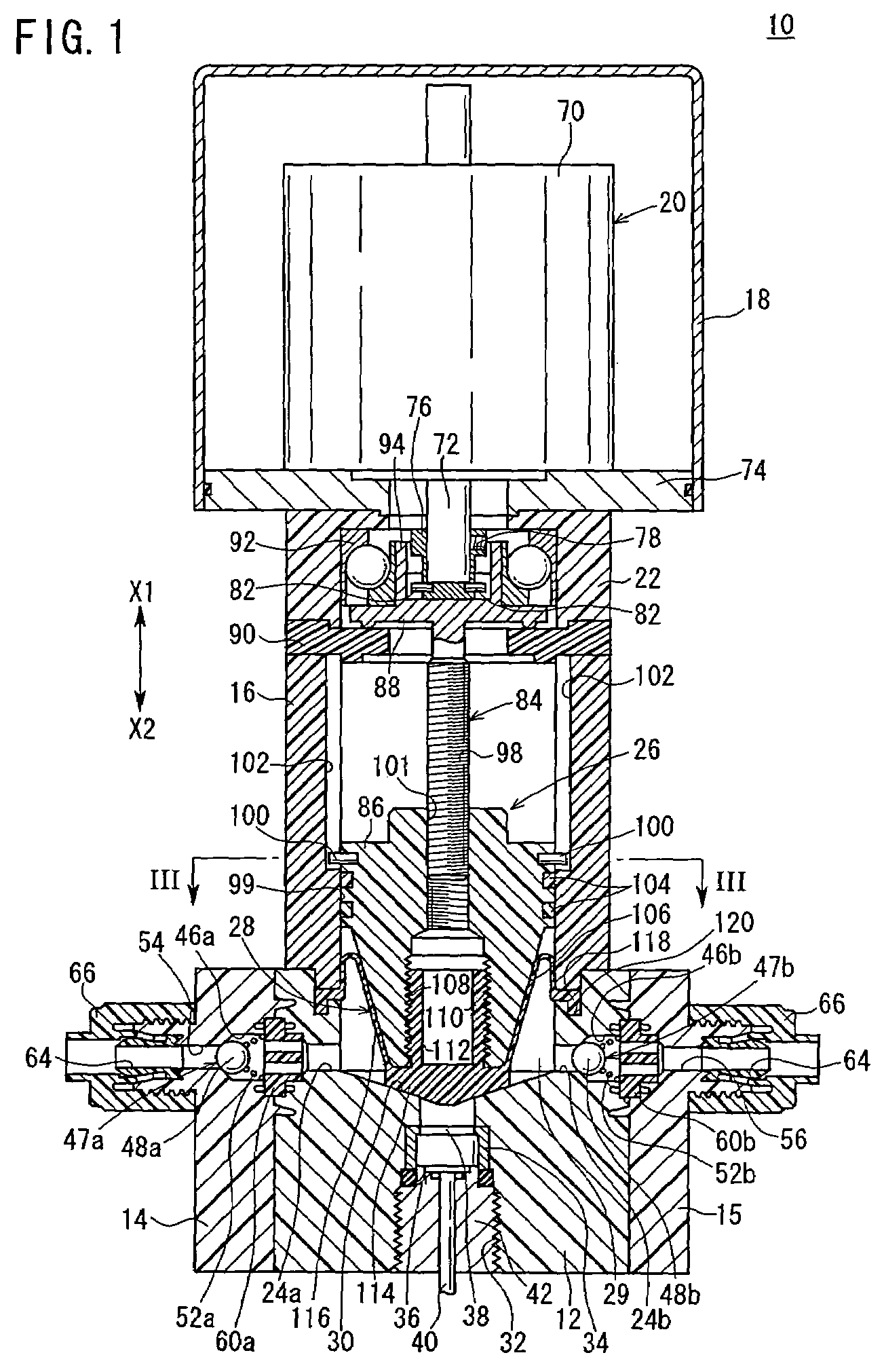
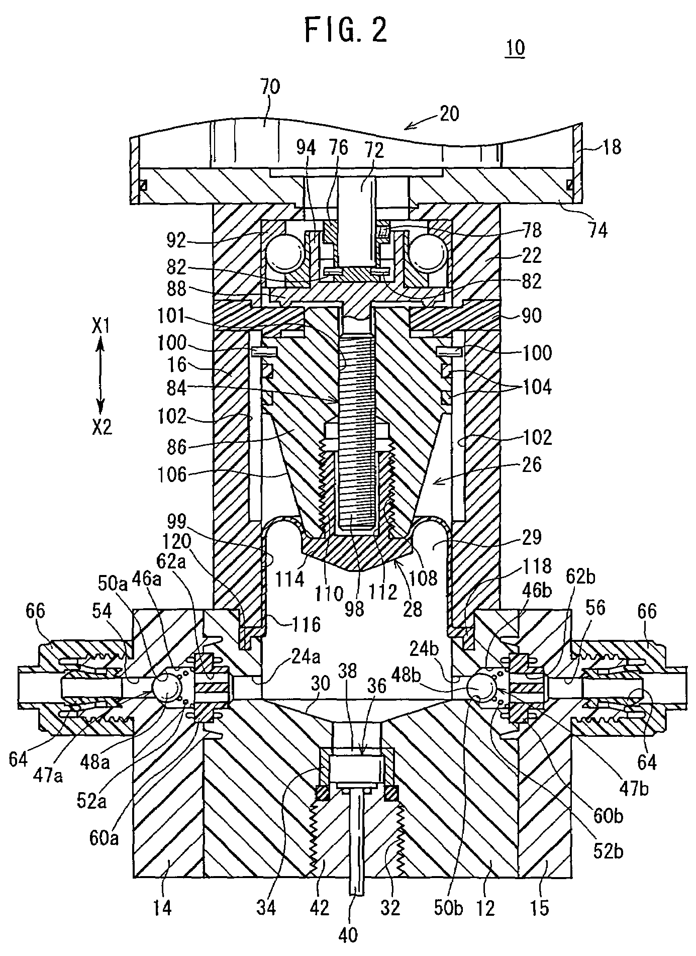
[0018]With reference to FIG. 1, reference numeral 10 indicates a constant rate discharge pump according to an embodiment of the present invention.

[0019]The constant rate discharge pump 10 comprises a body 12 in which fluid passages 24a, 24b for flowing the fluid are formed, first and second joint members 14, 15 which are connected to side portions of the body 12 and to which unillustrated tubes are detachably connected, a bonnet 16 which is connected to an upper portion of the body 12, and a driving section 20 which is provided in a cover member 18 arranged on the bonnet 16 and which is driven and rotated by an electric signal supplied from an unillustrated power source. The constant rate discharge pump 10 further comprises a holding member 22 which is interposed between the bonnet 16 and the driving section 20 for holding a bearing 92 as described later on, and a flow rate control mechanism 26 which controls the flow rate of the fluid flowing through the fluid passages 24a, 24b by ...


PUM


Abstract

A constant rate discharge pump comprises a rotary shaft which is rotatable together with a rotary driving source, a piston which is displaceable in an axial direction in a pump chamber of a body by the rotation of the rotary shaft and which has a tapered surface having diameters reduced downwardly on an outer circumference thereof, and a skirt section which is disposed on the piston and which extends radially outwardly. The constant rate discharge pump further includes a valve plug membrane of a resin material which is displaceable together with the piston, and a pressure sensor installed in the body which detects a pressure of a fluid flowing through the pump chamber.

Description

BACKGROUND OF THE INVENTION[0001]1. Field of the Invention[0002]The present invention relates to a pump apparatus which makes it possible to discharge a constant amount of a fluid all the time by controlling the flow rate of the fluid by rotation of a driving source.[0003]2. Description of the Related Art[0004]A constant rate discharge pump has been adopted in order to supply a constant amount of a chemical solution, a paint, a washing solution, or the like, for an apparatus of producing semiconductors or the like, a painting apparatus, and a medical apparatus.[0005]A bellows type pump is often used for the constant rate discharge pump. In the bellows type pump, the suction pressure and the discharge pressure are obtained by expanding / contracting bellows surrounding a shaft member, driven by a motor or the like.[0006]In this apparatus, the shaft member is displaced in the axial direction by the driving source such as the motor. The tip section of the shaft member is displaced in a p...

Claims


Application Information

Patent Timeline
Patent Type & Authority Patents(United States)
IPC IPC(8): F04B17/03F04B9/04F04B9/02F04B43/02F04B43/04
CPCF04B9/02F04B43/04F04B2205/03
Inventor FUKANO, YOSHIHIROSUZUKI, TAKAMITSU
Owner SMC CORP
Why Eureka
Try Eureka