Electrical contact

a technology of electric contact and contact plate, which is applied in the direction of coupling contact members, coupling device connections, transportation and packaging, etc., can solve the problems of friction corrosion, failure of electric automobile components associated with contact, and increased oxidation, so as to reduce friction coefficients and increase wear resistance

Inactive Publication Date: 2007-11-13
ROBERT BOSCH GMBH
View PDF16 Cites 17 Cited by
  • Summary
  • Abstract
  • Description
  • Claims
  • Application Information

AI Technical Summary

Benefits of technology

[0010]The electric contact according to the exemplary embodiment of the present invention, having a metallic substrate to which a structured contact layer is applied, has the advantage of an optimized tribological characteristic, which is adjustable via structuring. In particular, a contact layer of an electric contact having reduced friction coefficients and increased wear resistance may be manufactured via suitable structuring.
[0015]By introducing the nanodispersion into the contact layer matrix, the service life, in particular the number of insertion cycles and / or the friction corrosion resistance of the electric contact, may be increased.
[0016]The strength and hardness of the contact layer may thus be increased by introducing particles whose hardness is greater than that of the matrix. Particles of this type are made, for example, of Al2O3 which are dispersed in a matrix of tin or silver, for example. Alternatively, particles of yttrium oxide, zirconium oxide, titanium aluminide, titanium nitride, ruthenium alloy phases and / or the like may also be used. Introducing electrically conductive phases such as titanium nitride or ruthenium alloy phases as the particles dispersed in the matrix has the advantage that the electrical properties of the contact layer are not affected.
[0017]However, particles dispersed in the matrix, a silver matrix in particular, may also be formed by a solid-state lubricant. A solid-state lubricant of this type may be, for example, graphite or MOS2, and results in reduced friction forces and insertion forces which must be applied to connect the electric contact with a mating contact.
[0022]The micro-oil capsules introduced into the matrix represent carbon-containing islands in the structure and cause the friction forces and insertion forces to be optimized, increase the service life of the layer and the friction corrosion resistance.
[0024]In another embodiment of the electric contact according to the present invention, structuring is formed by a multilayer system which is made up of successive layers having varying chemical compositions. The friction coefficients of the contact layer may be reduced and its wear resistance increased also by using such a multilayer system.

Problems solved by technology

Tin alloys or tin layers, however, have the disadvantage that they tend to wear off due to their low hardness and the resulting low wear resistance upon frequent insertions or vibrations caused by the vehicle or the engine, which results in increased oxidation, known as friction corrosion.
Friction wear and / or friction corrosion may in turn result in failure of an electric automobile component associated with the contact in question, in particular a sensor, a control unit, or the like.
In tin or tin alloy layers of this type it is furthermore disadvantageous that the insertion forces for many applications are excessively high, because these contact layers have a strong tendency toward adhesion and high plastic deformability.
However, it has been found that thermotin has limited applicability, which may be shown in particular on the basis of chemical and abrasion testing.
Even in silver or gold layers previously used in electric contacts, oxidative wear of the substrate or of an intermediary layer used as an adhesion layer, often made of copper or nickel, may occur in the event of friction wear or flaking of the layer.

Method used


Image

  • Electrical contact
  • Electrical contact
  • Electrical contact

Examples


Embodiment Construction

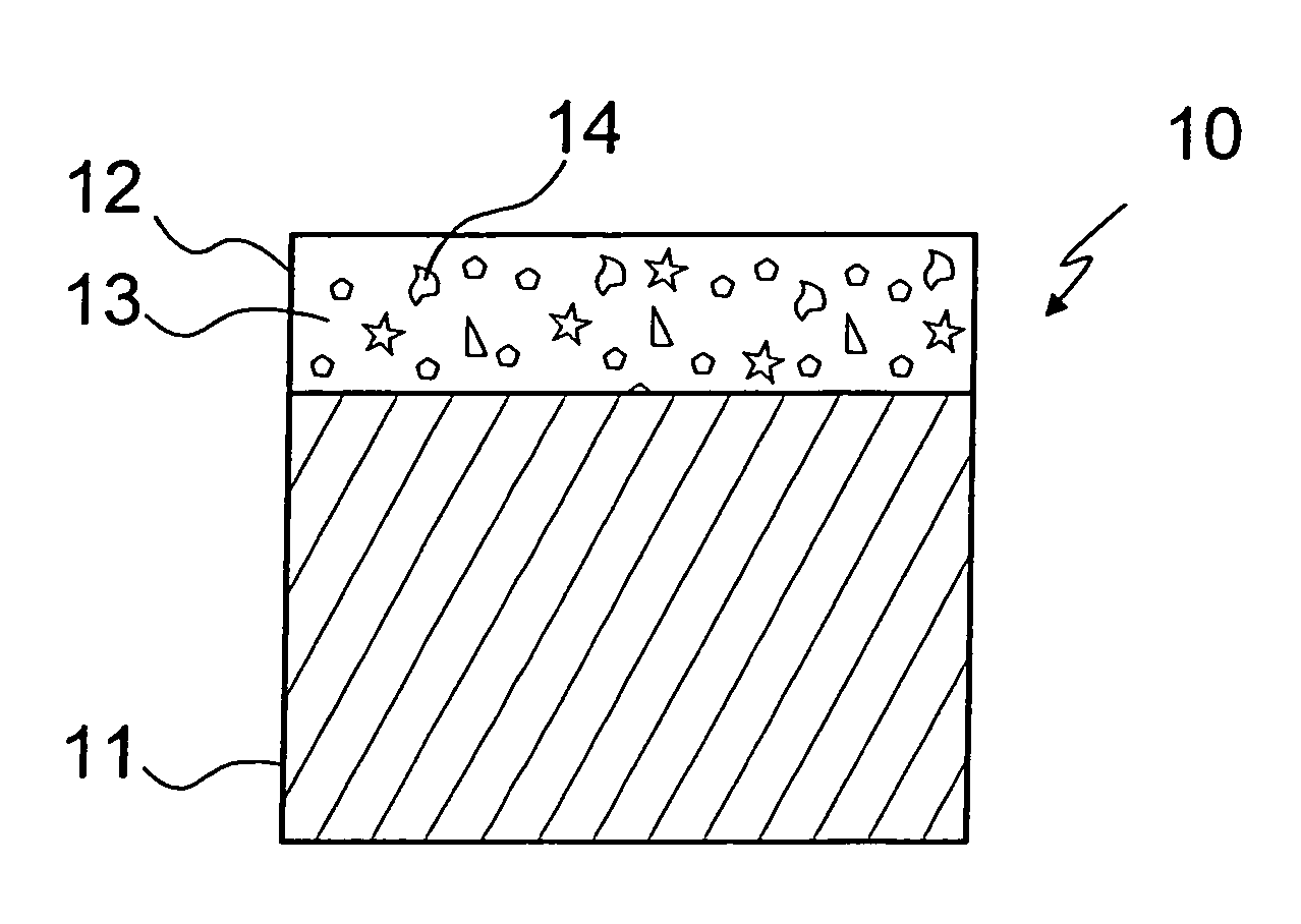
[0033]FIG. 1 schematically illustrates a surface of an electric contact 10, which is a contact of a plug-in connector for use in an automobile.

[0034]Electric contact 10 includes a substrate 11 which is manufactured from a copper-based alloy such as CuSn4, CuNi2Si or the like. Substrate 11 has a thickness of between 0.1 mm and 0.5 mm.

[0035]A contact layer 12 is applied to substrate 11 by an electrolytic method. Contact layer 12 has a layer thickness of between approximately 1 μm and 3 μm and has a matrix 13 made of tin. Hard particles 14 of aluminum oxide Al2O3 having a particle size of between 20 nm and 200 nm are distributed, i.e., “dispersed,” in matrix 13. Contact layer 12 thus represents a solid-state nanodispersion.

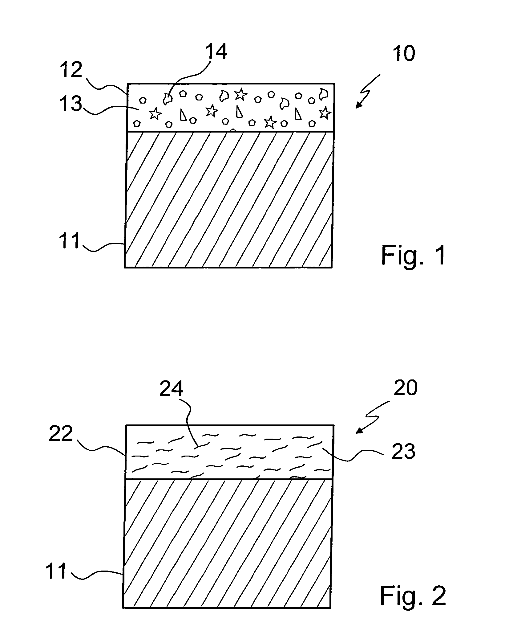
[0036]FIG. 2 schematically illustrates an electric contact 20, which is also a contact of a plug-in connector for use in an automobile.

[0037]Similar to the electric contact of FIG. 1, electric contact 20 includes a substrate 11 which is made of a copper-based alloy.

[...


PUM

PropertyMeasurementUnit
sizeaaaaaaaaaa
sizeaaaaaaaaaa
thicknessaaaaaaaaaa

Abstract

An electric contact, in particular an electric contact of a plug-in connector, has a metallic substrate to which a contact layer is applied. The contact layer is arranged as a structured layer.

Description

FIELD OF THE INVENTION[0001]The exemplary embodiment of the present invention is directed to an electric contact, in particular an electric contact of a plug-in connector.BACKGROUND INFORMATION[0002]An electric contact of this type is available and is used, for example, in the automobile industry.[0003]Such an electric contact includes a metallic substrate, which is normally made of a copper-based alloy such as CuSn4 bronze, CuNiSi or the like, on which a contact layer made of tin is situated. The contact layer may be a hot-tin-plated or electrolytically deposited layer which has a thickness of a few micrometers. An intermediary layer made of intermetallic compounds such as CuSn4, Cu5Sn6 is formed by diffusion on the boundary surface with the substrate when a tin contact layer is used. The intermediary layer is harder than the contact layer and may grow as a function of the temperature.[0004]Tin or a tin alloy is characterized by high ductility and good electric conductivity. Tin al...

Claims


Application Information

Patent Timeline
Patent Type & Authority Patents(United States)
IPC IPC(8): H01R13/02H01H1/02H01H1/023H01H1/027H01H1/60H01R13/03
CPCH01H1/02H01H1/60H01R13/03B32B15/018H01H1/023H01H1/027Y10T428/12486Y10T428/12708H01H2300/036
Inventor REHBEIN, PETERHAAS, VOLKER
Owner ROBERT BOSCH GMBH
Why Eureka
Try Eureka