Stationary computed tomography system and method

a computed tomography and imaging system technology, applied in material analysis using wave/particle radiation, instruments, nuclear engineering, etc., can solve the problems of large volume of wires, single end, disadvantageous sensitive performance of these systems to the length of interconnecting wires, etc., to facilitate the generation of radiation beams

Active Publication Date: 2007-11-13
GENERAL ELECTRIC CO
View PDF8 Cites 75 Cited by
  • Summary
  • Abstract
  • Description
  • Claims
  • Application Information

AI Technical Summary

Problems solved by technology

However, they are limited by the need to rotate the source and detector elements about the subject to obtain a 360-degree scan.
In addition, a large volume of wires is required to interconnect a system controller to the X-ray source drive circuits and the other functional blocks of the stationary CT system.
The performance of these systems is disadvantageously sensitive to the lengths of the interconnecting wires.
In addition, single ended, high impedance digital interconnections employed by these systems are highly susceptible to common mode noise.

Method used


Image

  • Stationary computed tomography system and method
  • Stationary computed tomography system and method
  • Stationary computed tomography system and method

Examples


Embodiment Construction

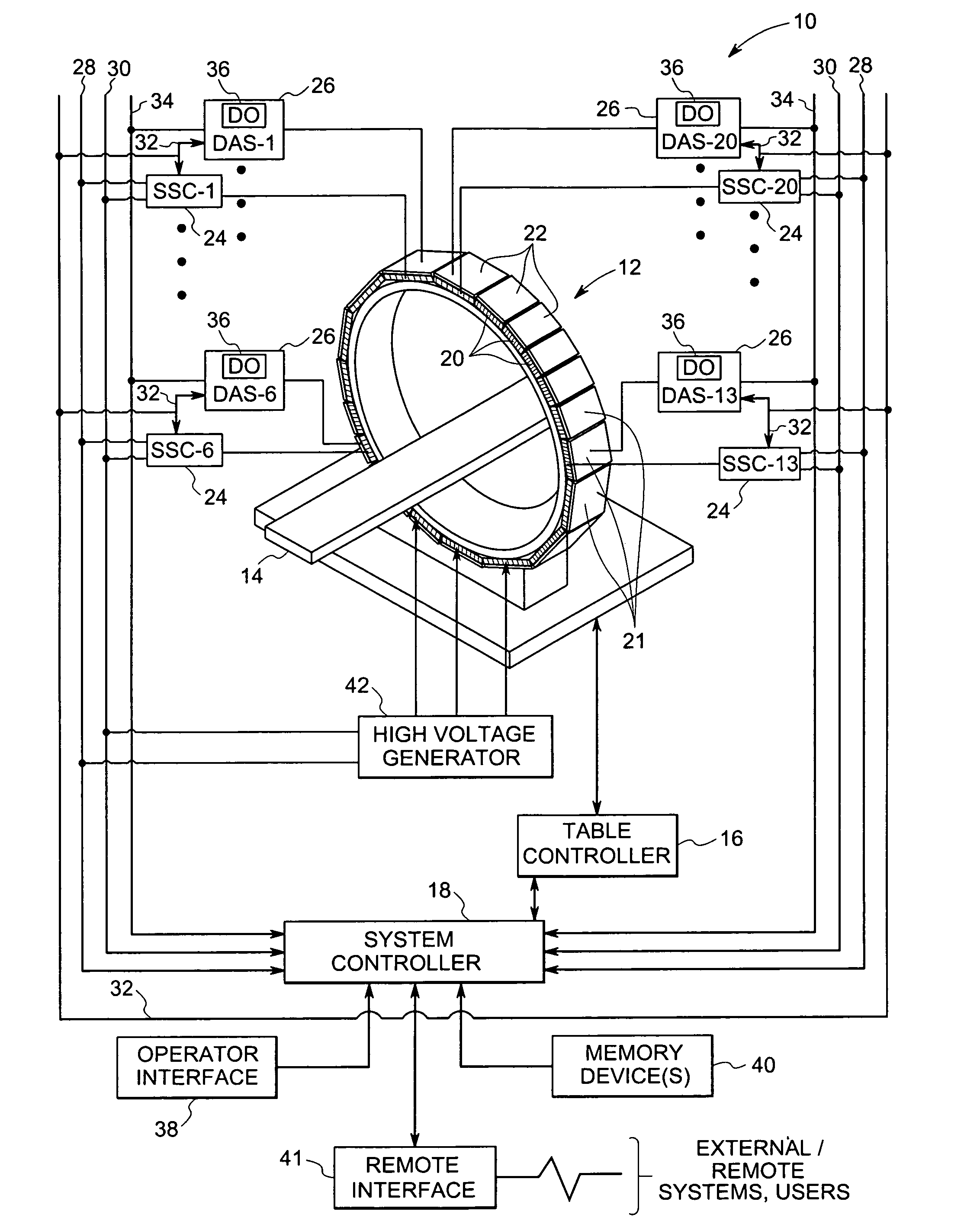
[0014]Turning now to FIG. 1, an exemplary stationary computed tomography (CT) system 10, in accordance with aspects of the present technique, is illustrated. As will be appreciated by those skilled in the art, the figures are for illustrative purposes and are not drawn to scale. The CT system 10 comprises a scanner 12 and may be configured to receive a table 14 or other support for a patient (not shown), or, more generally, an object (not shown) to be scanned. The table 14 may be moved through an aperture in the scanner 12 to appropriately position the object in an imaging volume or plane scanned during imaging sequences. The system 10 further includes a table controller 16 which may function under the direction of a system controller 18.

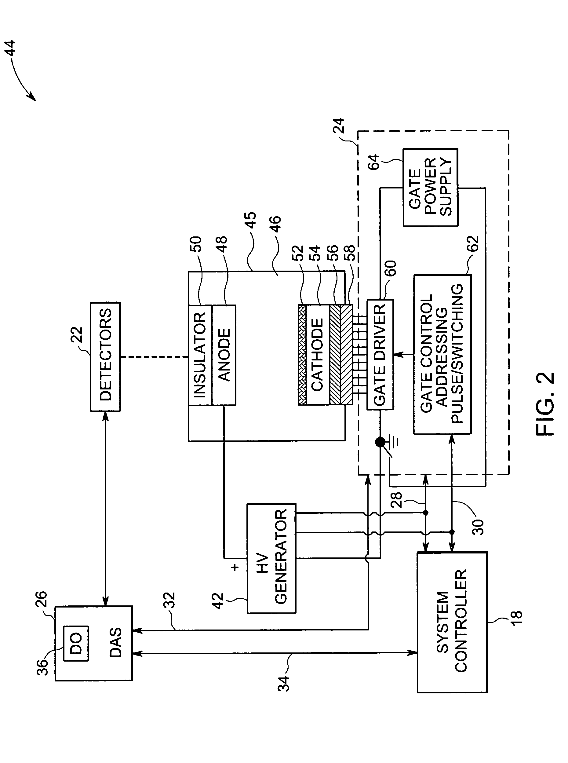
[0015]Further, the scanner 12 may be formed of a support structure and one or more stationary and distributed sources 20 of X-ray radiation and one or more stationary digital detectors 22. In accordance with an exemplary embodiment of the present te...


PUM


Abstract

A radiographic imaging system is presented. The system includes a system controller and a plurality of sub-system controllers. Each sub-system controller is configured to facilitate generation of a radiation beam through an imaging volume in a desired sequence. In addition, the system includes a first communication link configured to couple the system controller and each of the sub-system controllers, where the first communication link is configured to communicate sequencing commands and imaging protocol data. The system also includes a second communication link configured to couple the system controller and each of the sub-system controllers, where the second communication link is configured to communicate X-ray source event data. The X-ray source event data comprises a plurality of pulses of individually addressable radiation sources. Additionally, the system includes one or more detector sections configured to receive a transmitted radiation beam.

Description

BACKGROUND[0001]The invention relates generally to the field of computed tomography (CT) imaging systems, and more particularly to geometries and interconnection configurations for the stationary CT systems in which a single detector or multiple detectors and distributed radiation source elements are fixedly positioned in an imaging system scanner.[0002]Many applications exist for computed tomography imaging systems. Developed over recent decades, such imaging systems provide a powerful tool for imaging internal features of subjects of interest, typically presented as slices and volumes. In general, the systems consist of a source that directs X-ray radiation through the subject of interest onto a detector. As will be appreciated, the source of radiation may be any type of radiation that is able to penetrate the subject of interest. The X-ray source and detector, in traditional systems, are mounted on a rotational gantry and spun at a relatively high rotational rate (e.g., two revol...

Claims


Application Information

Patent Timeline
Patent Type & Authority Patents(United States)
IPC IPC(8): H05G1/70H05G1/00
CPCG01N23/046H05G1/70H05G1/10H01J2235/068G01N2223/419
Inventor DELGADO, ELADIO CLEMENTEREN, ZHIYUAN
Owner GENERAL ELECTRIC CO
Why Eureka
Try Eureka