
Howling suppression device and howling suppression method

a technology of howling suppression and suppression device, which is applied in the direction of transducer acoustic reaction prevention, line-transmission, interconnection arrangements, etc., can solve the problems of lessening the data-processing load of frequency analysis and reducing the memory capacity, so as to reduce the data-processing load of frequency analysis and reduce the memory capacity

Inactive Publication Date: 2007-11-13
PANASONIC CORP
View PDF10 Cites 2 Cited by
  • Summary
  • Abstract
  • Description
  • Claims
  • Application Information

AI Technical Summary

Benefits of technology

"The present invention provides an acoustic feedback suppression apparatus and method for suppressing acoustic feedback in a sound system. The apparatus includes a sound signal inputting system, filtering means, signal path identifying means, and filter coefficient specifying means. The filtering means filters out acoustic feedback components from the sound signals after adding the sound signals to different signal paths. The signal path identifying means identifies the signal paths that have acoustic feedback caused by converting the sound signals to digital data. The filter coefficient specifying means specifies filter coefficients for filtering out the acoustic feedback components on the identified signal paths. The apparatus can lessen the data-processing load and decrease the memory capacity by simultaneously suppressing the acoustic feedback of multiple channels. The acoustic feedback suppression method involves adding sound signals, judging if acoustic feedback is caused, calculating filter coefficients, and suppressing the acoustic feedback based on the filter coefficients."

Problems solved by technology

The acoustic feedback suppression apparatus thus constructed can lessen the data-processing load of the frequency analysis and decrease the capacity of the memory even if simultaneously suppressing the acoustic feedback of the sound signals respectively inputted to a plurality of channels.

Method used


Image

  • Howling suppression device and howling suppression method
  • Howling suppression device and howling suppression method
  • Howling suppression device and howling suppression method

Examples


Embodiment Construction

[0025]One of the preferred embodiments of the acoustic feedback suppression apparatus and the acoustic feedback suppression method according to the present invention will now be described in accordance with accompanying FIGS. 1A to 4.

[0026]The following description will now be directed to the construction of the preferred embodiment of the acoustic feedback suppression apparatus and the acoustic feedback suppression method according to the present invention.

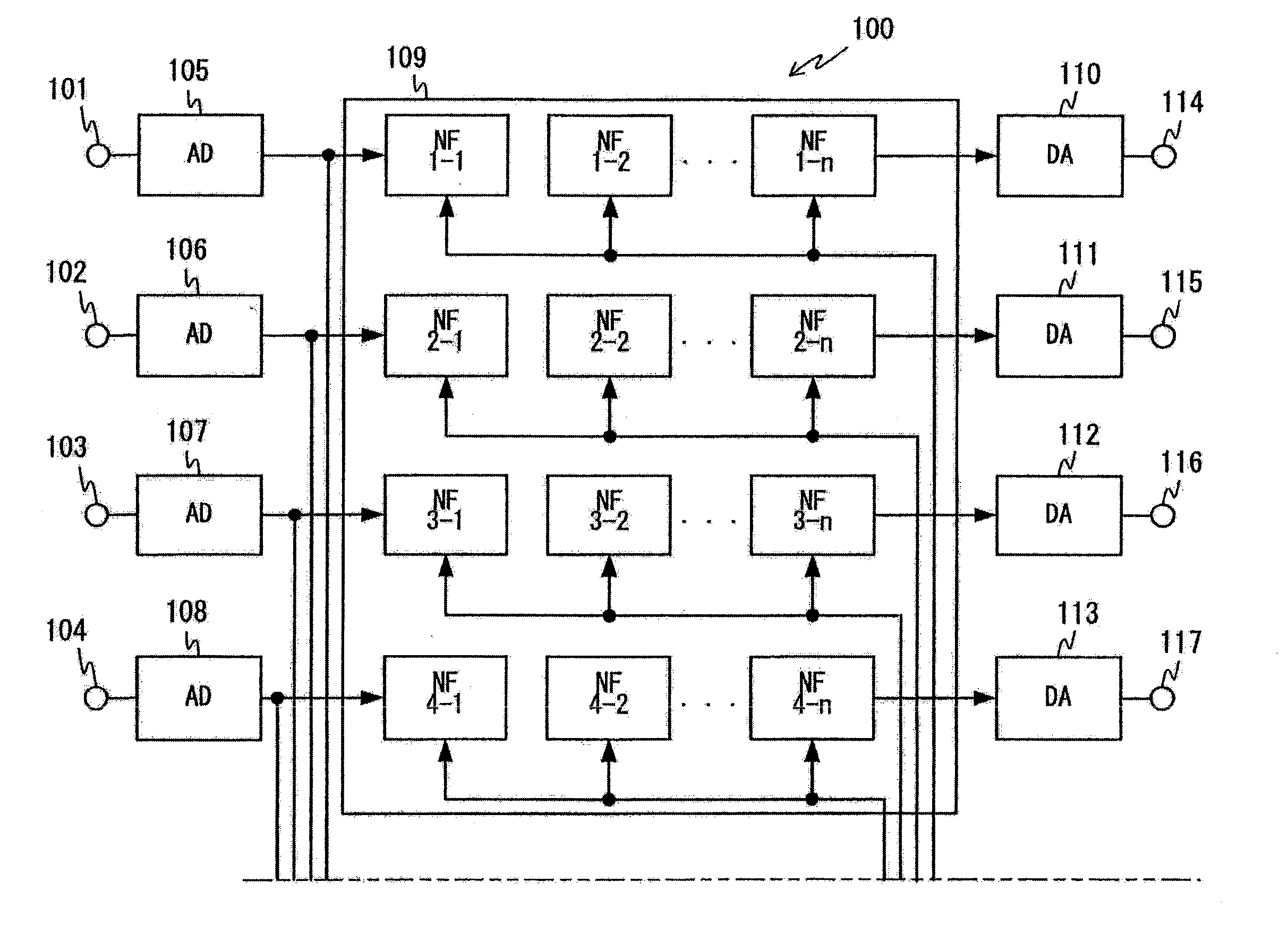
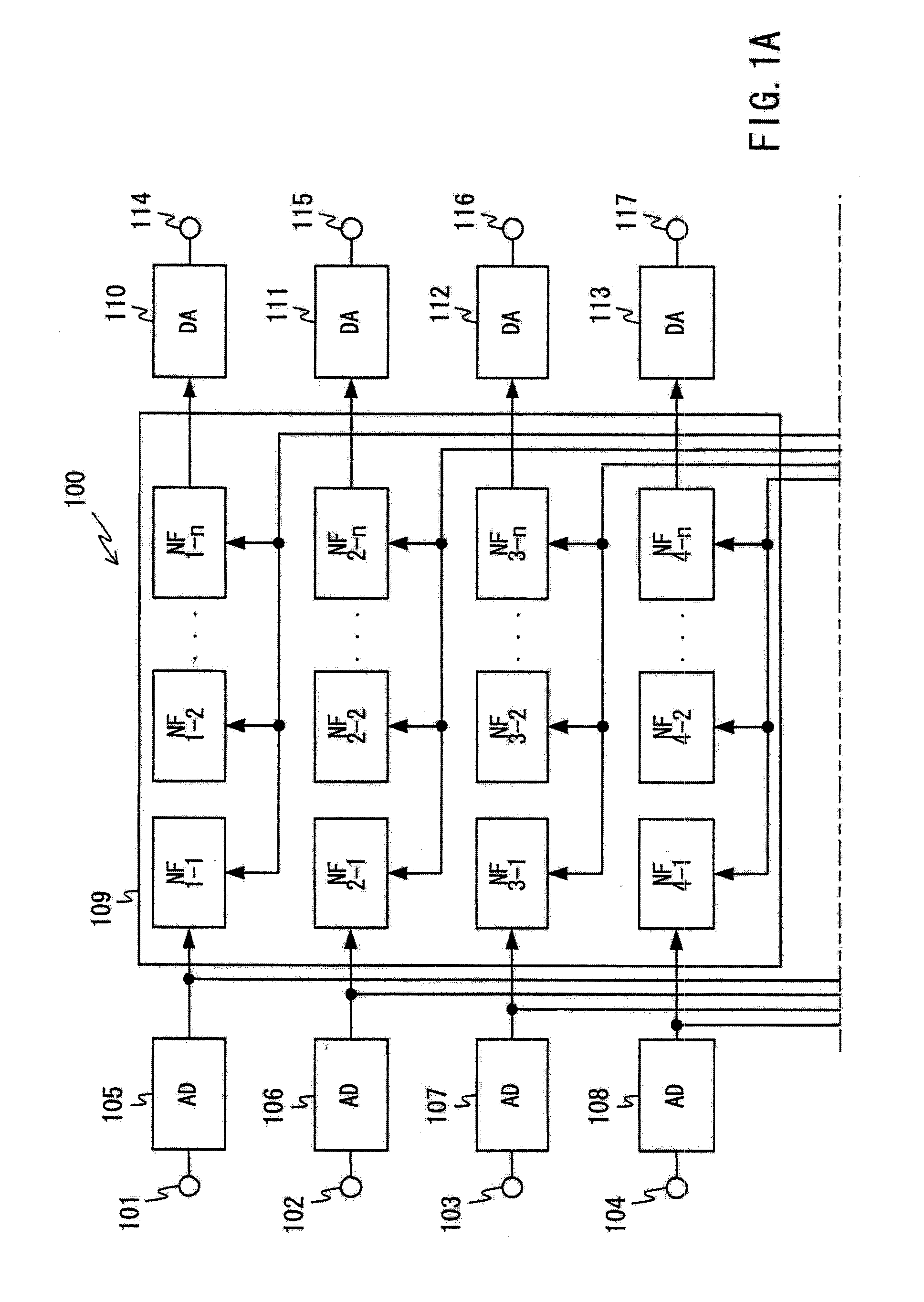
[0027]The acoustic feedback suppression apparatus 100 is shown in FIG. 1A as comprising a plurality of input terminals 101 to 104 respectively having analog sound signals inputted therein on first to fourth channels, a plurality of AD converters 105 to 108 for respectively converting the analog sound signals on the respective channels into digital sound signals, a notch filter unit 109 for filtering out acoustic feedback components from the digital sound signals on the respective channels, a plurality of DA converters 110 to 113 ...


PUM


Abstract

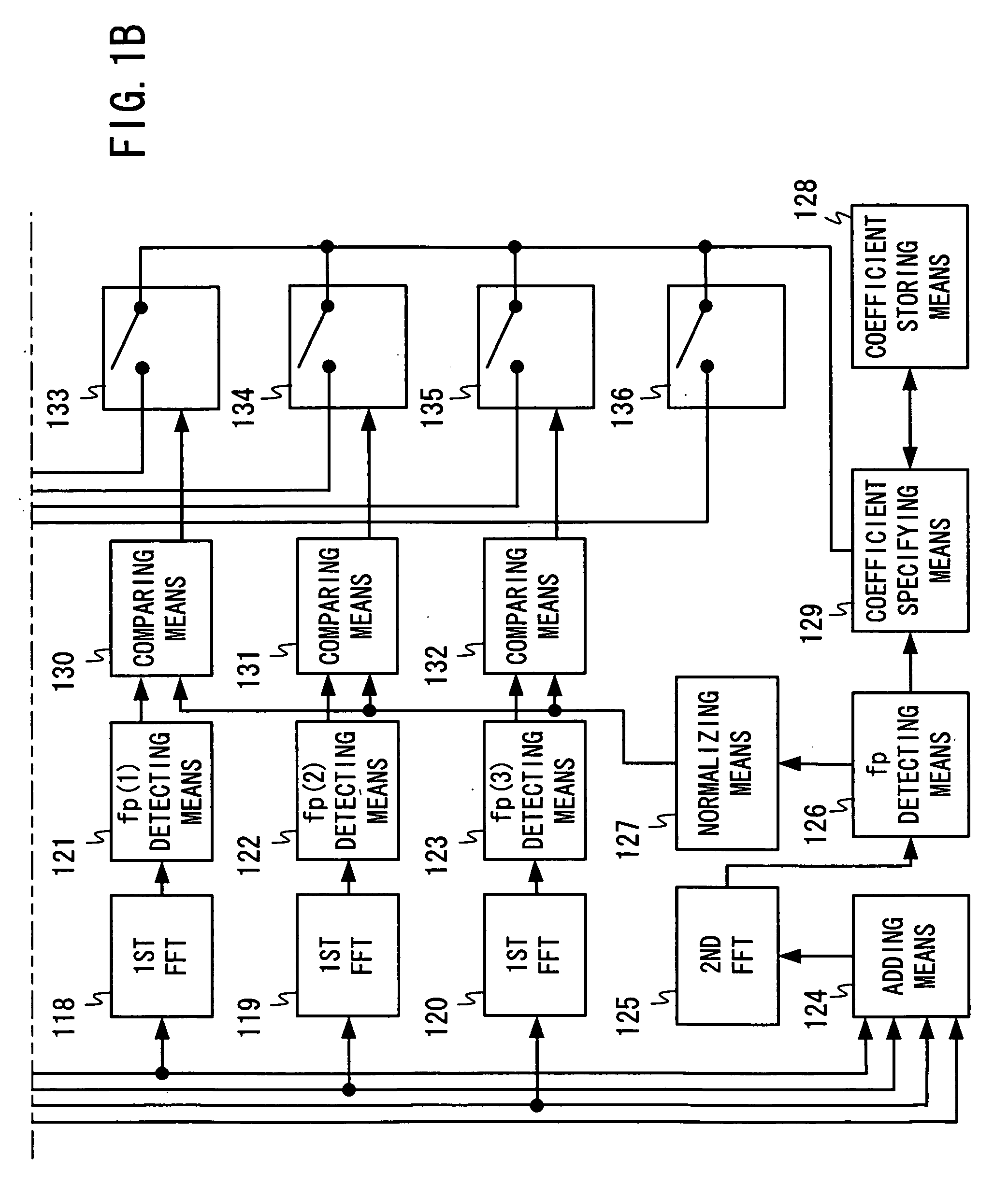
An acoustic feedback suppression apparatus according to the present invention comprises a notch filter (109) for filtering out acoustic feedback components, a plurality of first sample fast Fourier transformation means (118 to 120) for performing frequency analysis of every 512 data samples, a plurality of peak frequency detecting means (121 to 123) for detecting peak frequencies of respective channels, adding means (124) for adding signals on the respective channels, second sample fast Fourier transformation means (125) for performing frequency analysis of every 4096 data samples of the added signal, peak frequency detecting means (126) for detecting a peak frequency of the output signal outputted from the 4096 fast Fourier transformation means (125), and coefficient specifying means (129) for specifying filter coefficients of the notch filter (109).

Description

TECHNICAL FIELD [0001]The present invention relates to an acoustic feedback suppression apparatus and an acoustic feedback suppression method, and more particularly to an acoustic feedback suppression apparatus for and an acoustic feedback suppression method of suppressing acoustic feedback by judging whether or not the acoustic feedback is caused.BACKGROUND ART[0002]Up until now, there have been proposed a wide variety of conventional acoustic feedback suppression apparatuses of this type. One typical example of the conventional acoustic feedback suppression apparatuses is disclosed in Japanese Patent Laid-Open Publication No. 07-143034 (see page 4 and FIG. 1).[0003]The conventional acoustic feedback suppression apparatus 50 is shown in FIG. 5 as comprising an input terminal 1 having a sound signal inputted therein, an AD converter 2 for carrying out analog-to-digital conversion of the sound signal, a notch filter 3 connected to the AD converter 2, a DA converter 4 for carrying out...

Claims


Application Information

Patent Timeline
Patent Type & Authority Patents(United States)
IPC IPC(8): H04M9/08H04R3/02
CPCH04R3/02
Inventor ABE, RYOJI
Owner PANASONIC CORP
Learn More