
Impactable door

a technology of impact resistance and door frame, which is applied in the direction of wing accessories, corner/edge joints, wing arrangements, etc., can solve the problems of severe damage to the door frame, the severity of the impact that can be endured is quite limited, and the forklift also travels at considerable speed

Active Publication Date: 2007-11-20
ASI TECH
View PDF48 Cites 34 Cited by
  • Summary
  • Abstract
  • Description
  • Claims
  • Application Information

AI Technical Summary

Benefits of technology

"The present invention provides an impactable sliding door that addresses issues of impact and swinging panels. The door has a track panel that is suspended from the track and slides relative to the track so as to open and close the doorway. There is also a swinging panel that can pivot in either direction out of the plane of the track panel. The swinging panel is held in the plane of the track panel, in a normal position, by a detent mechanism. The detent allows the door to be released in either direction and the hinge connection of the swinging panel allows it to pivot in either direction out of the plane of the track panel. The swinging panel has a leading edge that is made of a foam or other highly compressible material, and a sensor can detect if the leading edge has been compressed or impacted. The door also has an impact resistant sheet added to the outside of the second panel in the area most likely to be hit by a fork lift. The soft leading edge of each door panel also contributes to sealing of the door when it is closed. The entire door panel assembly can be swung about a horizontal axis in at least one direction. The bottom of the door is connected in a releasable fashion to a track that is fastened to the wall so that if the door is impacted and swung away from the wall, the connection can release. The door automatically reengages to hold the bottom of the door adjacent to the wall when pivoted back into its normal operating position."

Problems solved by technology

Although the sliding doors open and close with considerable speed, the forklifts also travel with considerable speed.
When this happens, severe damage can occur to the door.
However, the materials of these doors have other disadvantages, including that they wear out, the severity of the impact that can be endured is quite limited, they are not easily cleaned, they absorb moisture, they can contribute to mold growth which is important in a food storage facility, and they can become torn, and do not present a structural or aesthetic appearance.

Method used


Image

  • Impactable door
  • Impactable door
  • Impactable door

Examples


Embodiment Construction

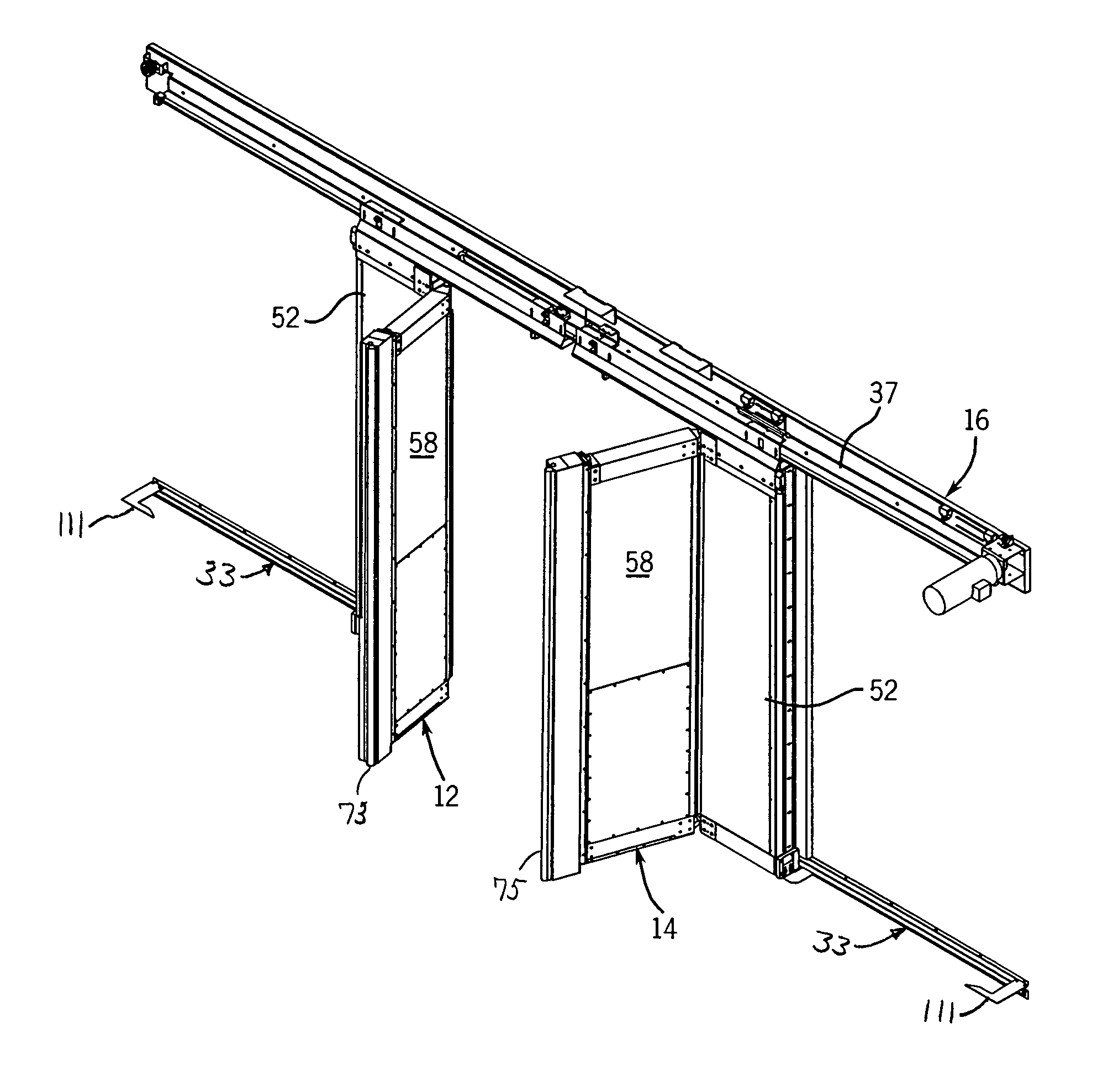
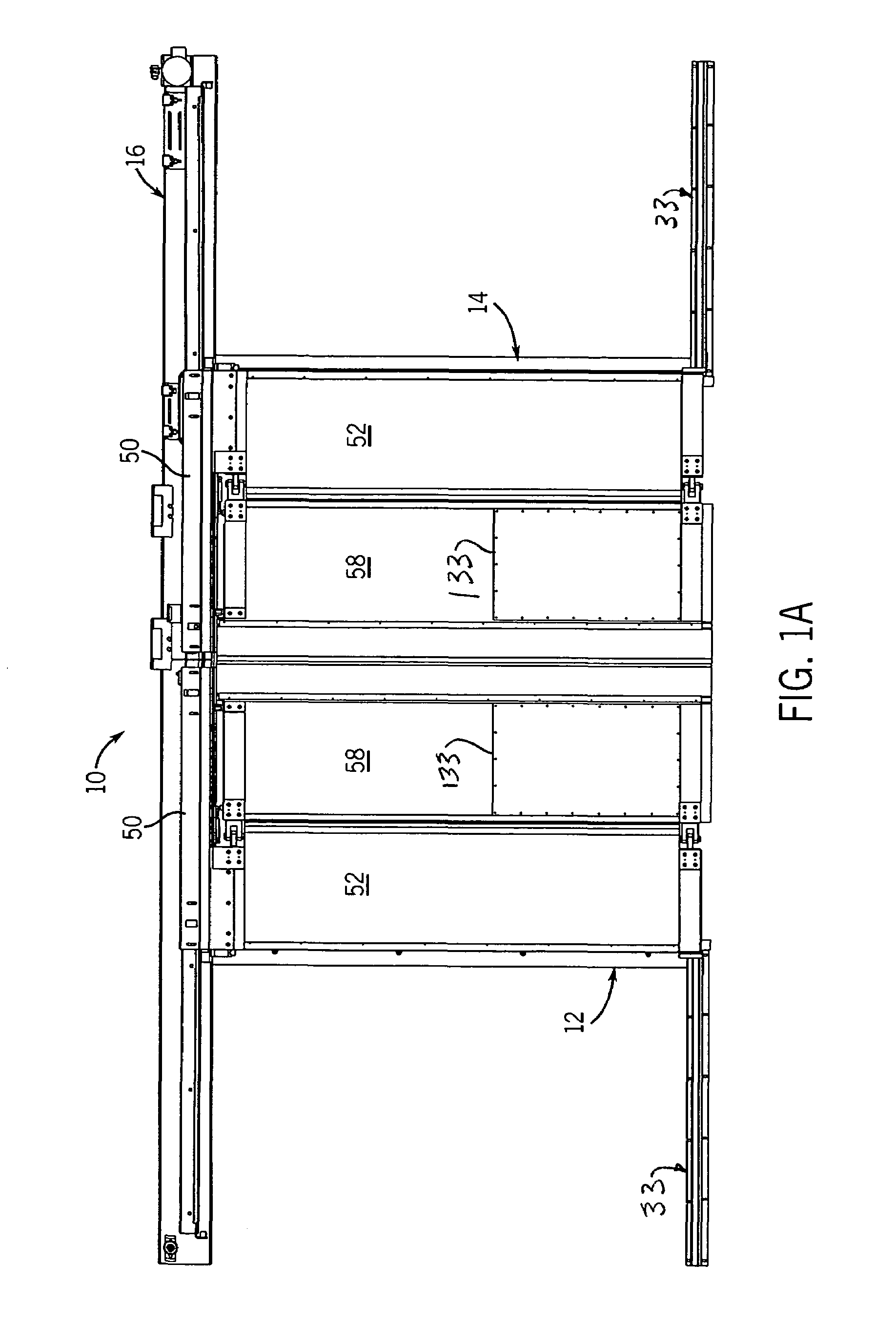
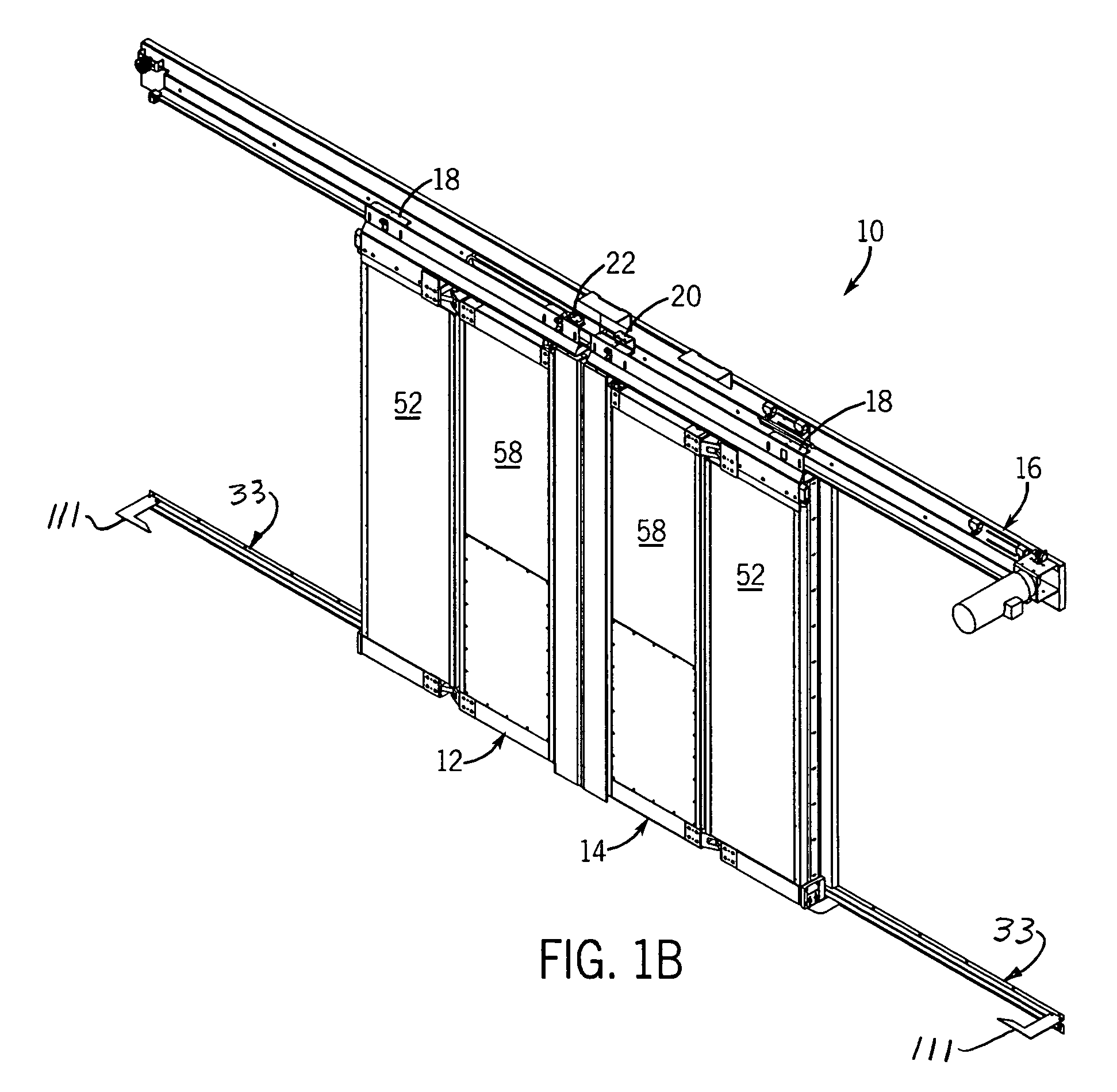
[0036]FIGS. 1A-D illustrate a door 10 including a left door panel assembly 12 and a right door panel assembly 14. The two door panel assemblies 12 and 14 are identical mirror images of one another. The door panel assemblies 12 and 14 are suspended from a track 16 in well-known manner by standard trolleys 18 at the outward top sides of each door panel assembly 12 and 14 and by a left-hand trolley 20 at the inward top side of the assembly 12 and by a right-hand trolley 22 at the inward top side of the assembly 14. The track 16 is bolted or otherwise affixed to a wall 30 (see FIG. 13) and, preferably, a lower rail 33 (FIG. 13) is also affixed to the wall 30 at the sides of the doorway opening, the lower rail 33 engaging a leaf spring extension of the door panel assembly to hold the lower end of the door panel assembly adjacent to the wall 30, as further described below. In well known fashion, the track 16 on each side of center angles down slightly toward center (in a bi-part door; dow...


PUM


Abstract

An industrial sliding door has one or more panel assemblies, each panel assembly having a track panel secured to a header and a swinging panel hinged at the inner edge of the track panel to pivot in either direction about a vertical axis if the swinging panel is impacted by a vehicle such as a fork lift. Both panels can also pivot in at least one direction about a horizontal axis. A rail mounted stationary relative to the doorway at the lower edge of the door holds the lower edge of the door in proximity to the doorway and is disengagable if the door is hit from the opposite side, to permit the door panel assembly to swing about the horizontal axis away from the doorway. The swinging panel is held by a detent in the plane of the track panel in a normal position.

Description

CROSS-REFERENCE TO RELATED APPLICATION[0001]This claims the benefit of the filing date of U.S. Provisional Patent Application Ser. No. 60 / 463,749 filed Apr. 17, 2003.STATEMENT CONCERNING FEDERALLY SPONSORED RESEARCH OR DEVELOPMENT[0002]Not applicable.FIELD OF THE INVENTION[0003]This invention relates to industrial doors, and in particular to a sliding industrial door that has features built into it to make it capable of enduring an accidental impact.BACKGROUND OF THE INVENTION[0004]Sliding doors for industrial applications are well known. For example, for a large scale industrial freezer, in which forklift trucks are continually coming in and out of the freezer, insulated sliding doors have been used. The sliding doors are typically suspended by trolleys that have wheels engaged on tracks which are mounted to the wall over the doorway. There may also be tracks on the walls at the bottom of the door to hold the bottom of the door close to the doorway. Two panels are typically provide...

Claims


Application Information

Patent Timeline
Patent Type & Authority Patents(United States)
IPC IPC(8): E05D15/06E05D15/26E05F15/14
CPCE05D15/54E05F15/643E05D15/0604E05D15/264E05D2015/586E05Y2201/214E05Y2201/232E05Y2800/407E05Y2201/11E05Y2600/40E05Y2900/11E05D2015/482E05Y2900/132
Inventor WEISHAR, WILLIAM B.ENDTER, JOSEPH M.
Owner ASI TECH
Learn More