Orientation device for a core sample

a core sample and orientation device technology, applied in survey, drilling accessories, borehole/well accessories, etc., can solve the problems of reducing the actual drilling time, affecting the accuracy of core sampling, and breaking the core by itsel

Inactive Publication Date: 2007-11-20
IMDEX TECH AUSTRALIA PTY LTD
View PDF6 Cites 55 Cited by
  • Summary
  • Abstract
  • Description
  • Claims
  • Application Information

AI Technical Summary

Benefits of technology

[0007]It is an object of the present invention to provide an orientation device for a core sample which does not require core breaking for operation and can be incorporated into a standard core drill so that it does not require separate tripping.

Problems solved by technology

Nevertheless, one drawback of the BALLMARK system is that it only operates by the actual breaking of the core.
However, in highly fractured or broken ground, the core breaks by itself during the drilling process.
A substantial drawback with this system is that it requires separate tripping of the tool down the hole which takes substantial time thereby reducing actual drilling time and substantially increasing the cost of coring.

Method used


Image

  • Orientation device for a core sample
  • Orientation device for a core sample
  • Orientation device for a core sample

Examples


Embodiment Construction

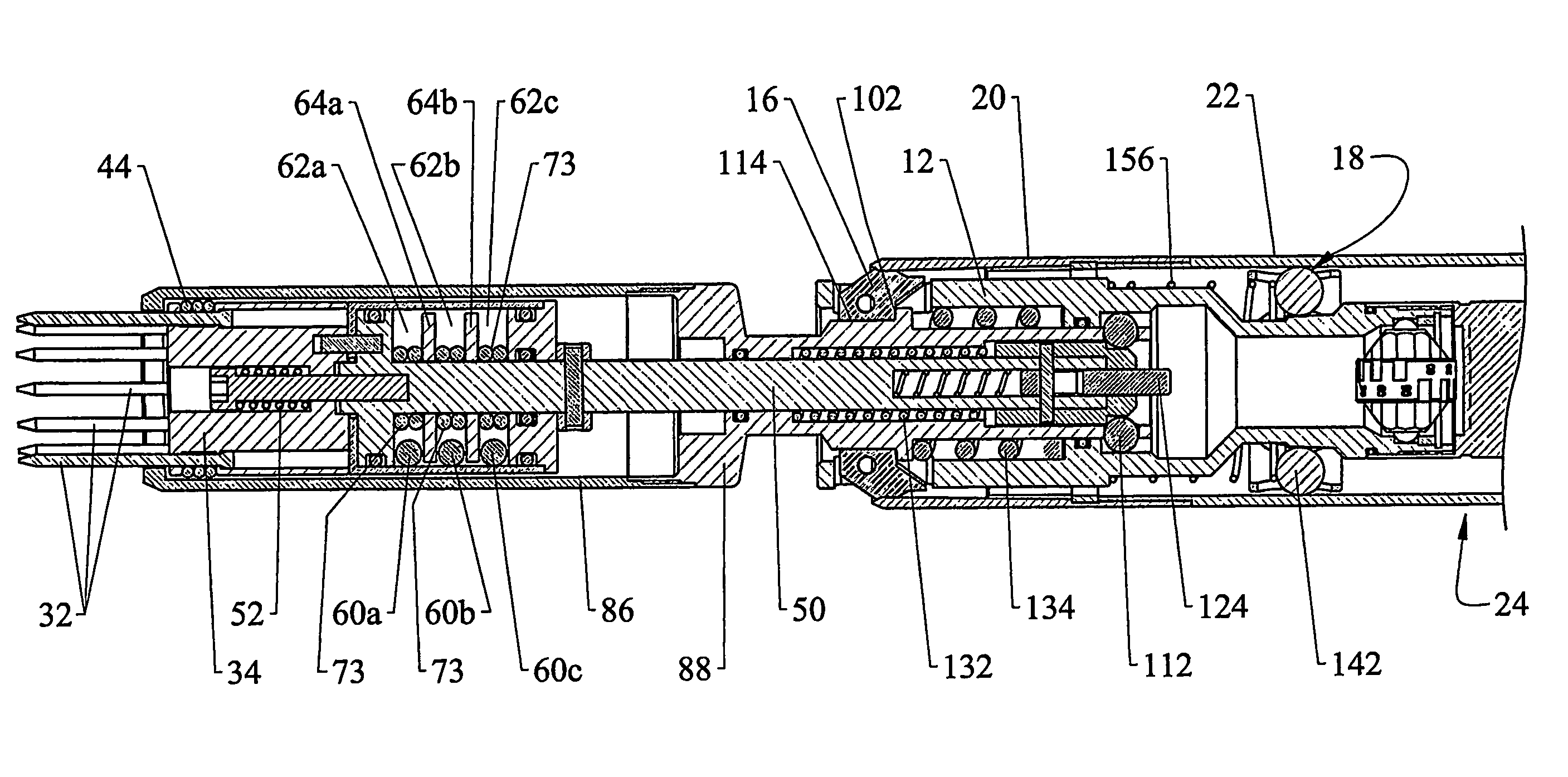
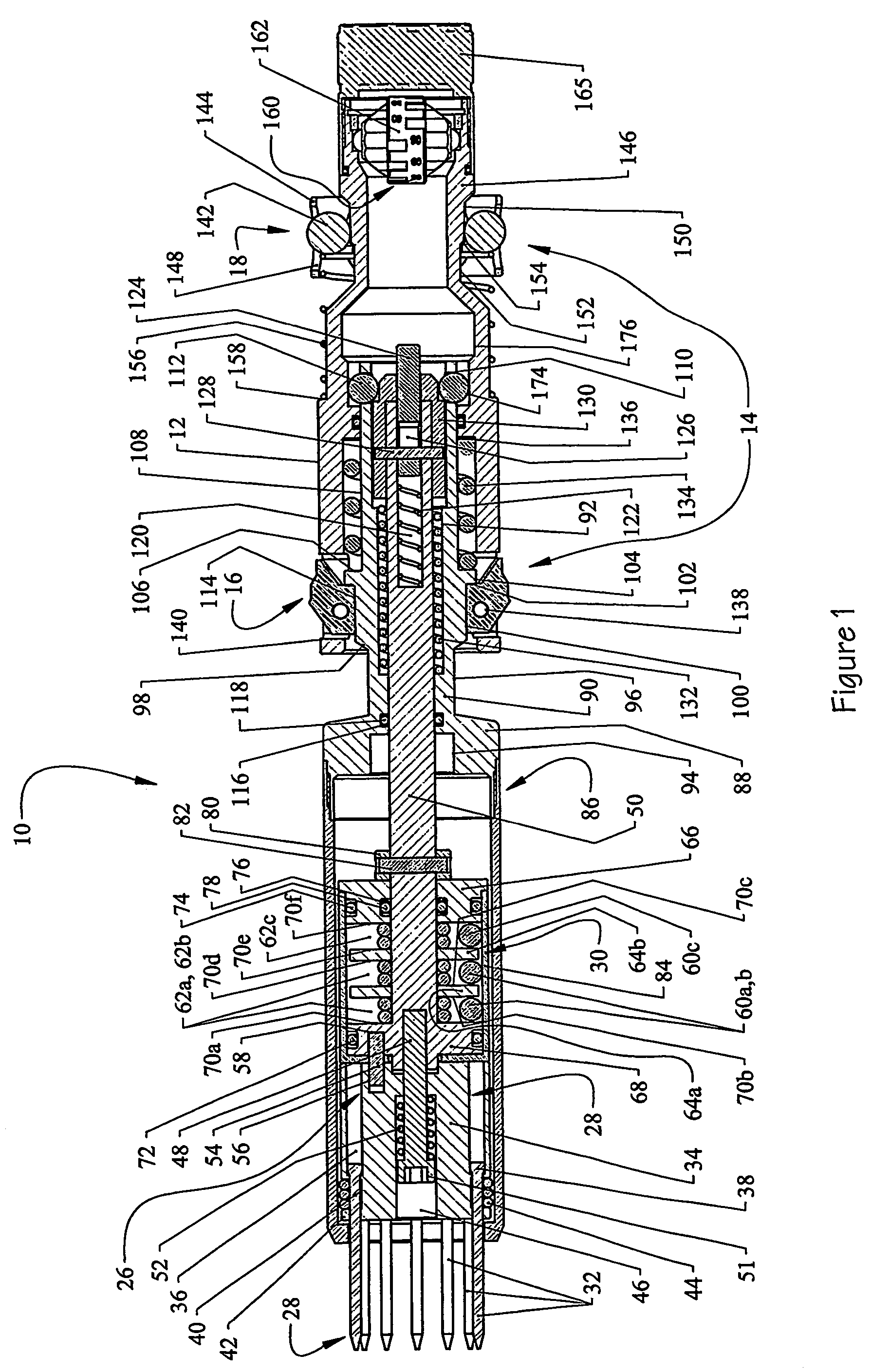
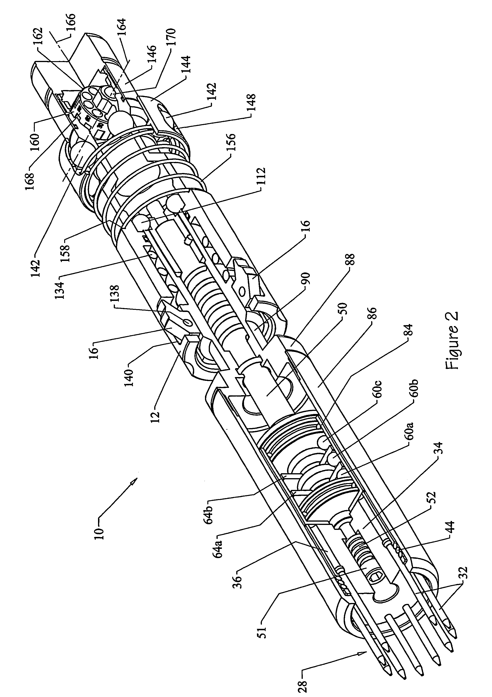
[0050]Referring to FIGS. 1-6 of the accompanying drawings, an embodiment of the orientation device 10 in accordance with the present invention includes a main body 12 provided with a latching system 14 which includes first latches 16 and second latches 18. (As described in greater detail hereinafter, the second latches 18 are in the form of a braking system). The latching system 14 operates to releasably latch the device 10 to a core lifter case assembly 20 (see FIG. 3) which incorporates a core lifter coupled to a core tube 22 of a core drill 24 used for cutting a core sample of the ground. The core lifter case assembly 20, core tube 22, and core drill 24 are of conventional construction and do not of themselves form part of the present invention.

[0051]A core orientation indicating means (hereinafter referred to as “core orientator”) 26 is slidably coupled to the main body 12. The core orientator 26 provides an orientation reference for the core sample cut by the core drill 24 by a...


PUM


Abstract

Core orientator for a core drill includes a face orientator and a bottom orientator supported by a shaft which extends into a shroud. A tubular extension is coupled to the shroud and is slidably coupled to a main body. The main body includes first and second latches. The first latches releasably lock the device to a core lifter case assembly disposed within the core drill, to selectively prevent the device from advancing in an uphole direction within the core drill. The latching system operates to prevent the device from falling out of the core drill. Face orientator includes a plurality of pins which can move axially to provide a plurality of profile reference points to a facing surface of a hole to be drilled. The bottom orientator includes a plurality of balls disposed within respective braces.

Description

FIELD OF THE INVENTION[0001]The present invention relates to an orientating device for providing an indication of the orientation of a ground core sample cut by a core drill.BACKGROUND OF THE INVENTION[0002]Core sampling is typically employed to allow geological surveying of the ground for purposes of exploration and / or mine development. Analysis of the material within the core sample provides information of the composition of the ground. However in order to map, for example a vein of ore, it is necessary to also have knowledge of the orientation of the core sample relative to the ground from which it was cut.[0003]Several systems are already known for orientating core samples. One such system is the BALLMARK (Trademark) system which is described in International Application No. WO 00 / 75480. This system utilises a soft metal disk and a free running metal ball which are incorporated into a conventional inner tube back end or head assembly. The system utilises the force generated duri...

Claims


Application Information

Patent Timeline
Patent Type & Authority Patents(United States)
IPC IPC(8): E21B25/16E21B10/02E21B31/20E21B47/024
CPCE21B25/16E21B47/024E21B31/20
Inventor BEACH, ANDREWMCLEOD, GAVIN
Owner IMDEX TECH AUSTRALIA PTY LTD
Why Eureka
Try Eureka