
Structure for mounting a turboprop under an aircraft wing

a technology for aircraft wings and structures, applied in the direction of machines/engines, mechanical apparatus, transportation and packaging, etc., can solve the problem that the structure cannot resist the torque generated by the entire engin

Active Publication Date: 2007-11-20
AIRBUS OPERATIONS (SAS)
View PDF7 Cites 21 Cited by
  • Summary
  • Abstract
  • Description
  • Claims
  • Application Information

AI Technical Summary

Benefits of technology

The invention proposes a mounting structure for a high power turboprop under an aircraft wing that can resist the engine torque generated during operation of the turboprop. The mounting structure comprises a rigid structure composed of a box and lateral connecting rods that resist the engine torque. The design of the mounting structure satisfies requirements for resistance to engine torque, mass, and displacement of the nozzle of the turboprop. The mounting structure also allows for vertical placement of the turboprop and provides access for mounting conventional equipment. The specific arrangement of the lateral connecting rods and the forward and aft fasteners ensure effective resistance to forces in the vertical and transverse directions. The invention provides a more efficient and effective mounting structure for high power turboprop engines.

Problems solved by technology

Studies carried out showed that considering technological feasibility limits for connecting rods for a conventional lattice type structure, this type of structure cannot resist the entire engine torque generated for power values which can be more than 230000 N.m.

Method used


Image

  • Structure for mounting a turboprop under an aircraft wing
  • Structure for mounting a turboprop under an aircraft wing

Examples


Embodiment Construction

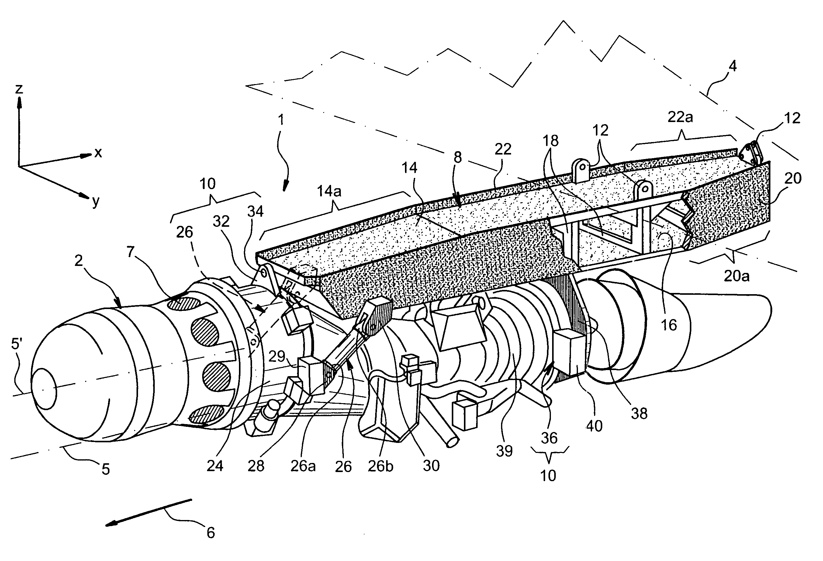
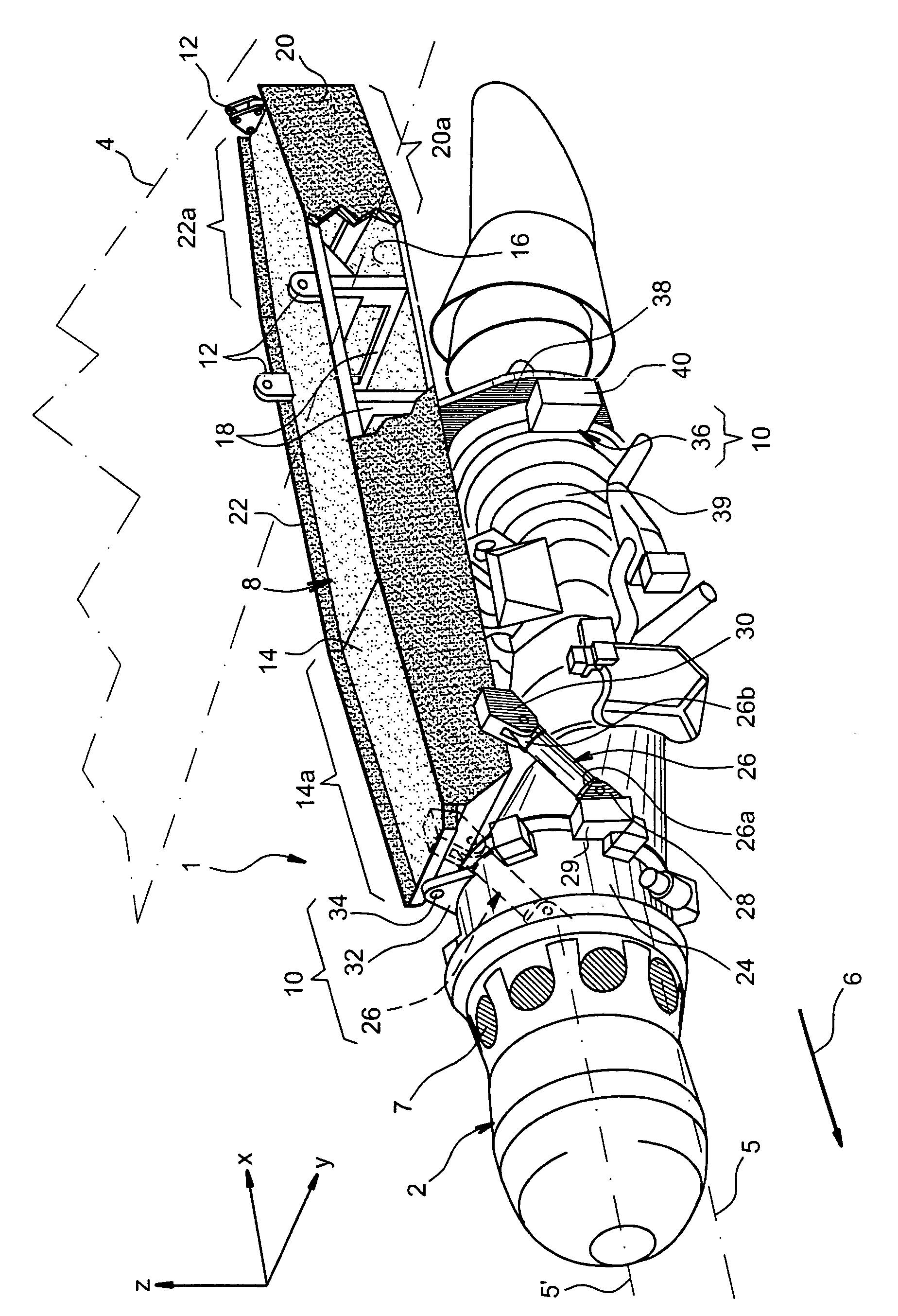
[0031]The single FIGURE shows a mounting structure 1 according to a first preferred embodiment of this invention, this structure 1 being designed to suspend a turboprop 2 under an aircraft wing shown only diagrammatically for obvious reasons of clarity, and generally denoted by the numeric reference 4.

[0032]Throughout the following description, by convention, X is the direction parallel to a longitudinal axis 5 of the turboprop 2, Y is the transverse direction relative to the aircraft, and Z is the vertical direction or the direction radially outwards from the turboprop 2 towards the mounting structure 1, these three directions being orthogonal to each other. It is noted that the longitudinal axis 5 of the turboprop 2 should be considered as being the longitudinal axis of the engine casing, and not the longitudinal axis of its propeller 7 (for which the blades are shown). The longitudinal axis of the propeller 7 is indicated by numeric reference 5′ on the single FIGURE. It is noted ...


PUM


Abstract

A structure for mounting a turboprop under an aircraft wing includes a rigid structure and a device for fastening the turboprop on the rigid structure. The rigid structure is composed of a box, and the device for fastening includes at least two lateral connecting rods resisting the engine torque generated by the turboprop, the connecting rods being arranged on each side of the box and each having a forward end connected to a gear box of the turboprop, and an aft end connected to the box.

Description

TECHNICAL DOMAIN[0001]This invention relates to a structure for mounting or suspending a turboprop under an aircraft wing.[0002]This type of structure may be used on any type of aircraft comprising turboprops suspended under its wing. In this respect, it is particularly suitable for use on aircraft fitted with turboprops capable of outputting high power, more than 10000 horsepower.STATE OF THE PRIOR ART[0003]On existing aircraft, engines are suspended under or are mounted above the wing by complex Engine Mounting Structures (EMS).[0004]These structures are designed particularly to transmit static and dynamic forces generated by engines, such as weight, thrust or different dynamic forces, to the wing.[0005]In the special case of a turboprop, three main criteria are taken into account to design the associated mounting structure, namely resistance to engine torque, the mass of this structure and finally the limitation to the displacement of the turboprop nozzle relative to the mounting...

Claims


Application Information

Patent Timeline
Patent Type & Authority Patents(United States)
IPC IPC(8): B64D27/26B64D27/12B64D27/18B64D27/40
CPCB64D27/12B64D27/26B64D2027/264B64D27/402B64D27/404B64D27/40
Inventor MACHADO, STEPHANECASSAGNE, JEROMEDEL BLANCO, ANTHONYMARTIN, YVONCHAMBREUIL, ARNAUD
Owner AIRBUS OPERATIONS (SAS)
Learn More