Method and composition for inhibiting lost circulation during well operation

a well and circulation technology, applied in the direction of fluid removal, chemistry apparatus and processes, borehole/well accessories, etc., can solve the problems of increasing the loss of drilling fluids beyond an acceptable limit, asbestos is undesirable for widespread commercial use, and practically all of the drilling fluid may be lost to the formation

Active Publication Date: 2007-11-20
TURBO CHEM INT
View PDF23 Cites 66 Cited by
  • Summary
  • Abstract
  • Description
  • Claims
  • Application Information

AI Technical Summary

Benefits of technology

[0013]A composition and method for reducing lost circulation and seepage loss of drilling fluids in drilling operations is provided. In one embodiment of the present invention, a drilling fluid for reducing circulation loss is provided comprising a liquid carrier, and a mixture of lignite, phenol-formaldehyde resin solids, and fibrous particles, wherein the liquid carrier is an oil based or synthetic drilling mud and the mixture is added to the liquid carrier at a concentration of between 1 and 50 pounds per barrel of liquid carrier, said mixture comprising between 15 and 35 parts by weight lignite, between 15 and 35 parts by weight phenol-formaldehyde resin solids, and between 35 and 65 parts by weight fibrous particles. The mixture can comprise between 20 and 30 parts by weight lignite, between 20 and 30 parts by weight phenol formaldehyde resin solids, and between 40 and 60 parts by weight fibrous particles. The mixture can comprise between 22 and 28 parts by weight lignite, between 22 and 28 parts by weight phenol-formaldehyde resin solids, and between 45 and 55 parts by weight fibrous particles. The mixture can be added at a concentration of between 5 and 20 pounds per barrel of drilling fluid.
[0016]In another embodiment, a method for substantially inhibiting fluid loss in subterranean drilling operations is provided, comprising: (a) preparing a drilling fluid additive comprising phenol-formaldehyde, lignite and a fibrous particulate material; (b) mixing the additive into a drilling fluid at a concentration between 1 and 50 pounds per barrel of drilling fluid; and (c) circulating the drilling fluid and additive mixture through a drill string and into the well bore. The additive can comprise between 15 and 35 parts by weight lignite, between 15 and 35 parts by weight phenol-formaldehyde resin, and between 30 and 70 parts by weight fibrous particles. The additive can comprise between 20 and 30 parts by weight lignite, between 20 and 30 parts by weight phenol-formaldehyde resin, and between 40 and 60 parts by weight fibrous particles. The phenol-formaldehyde resin can be chemically inert. The additive can be mixed into the drilling fluid at a concentration of between 5 and 20 pounds per barrel of drilling fluid.

Problems solved by technology

Frequently, undesirable formation conditions are encountered in which substantial amounts, or in some cases, practically all of the drilling fluid may be lost to the formation.
However, formations are frequently encountered that are so porous as to increase the loss of drilling fluids beyond an acceptable limit despite the use of traditional lost circulation additives.
However, due to its carcinogenic nature, asbestos is undesirable for widespread commercial use.
While materials for the prevention of loss via seepage and circulation loss are well known for water based drilling muds, loss control additives for synthetic or oil based muds are particularly desirable due to the high costs associated with these replacement of these drilling fluids.

Method used


Image

  • Method and composition for inhibiting lost circulation during well operation

Examples


example 1

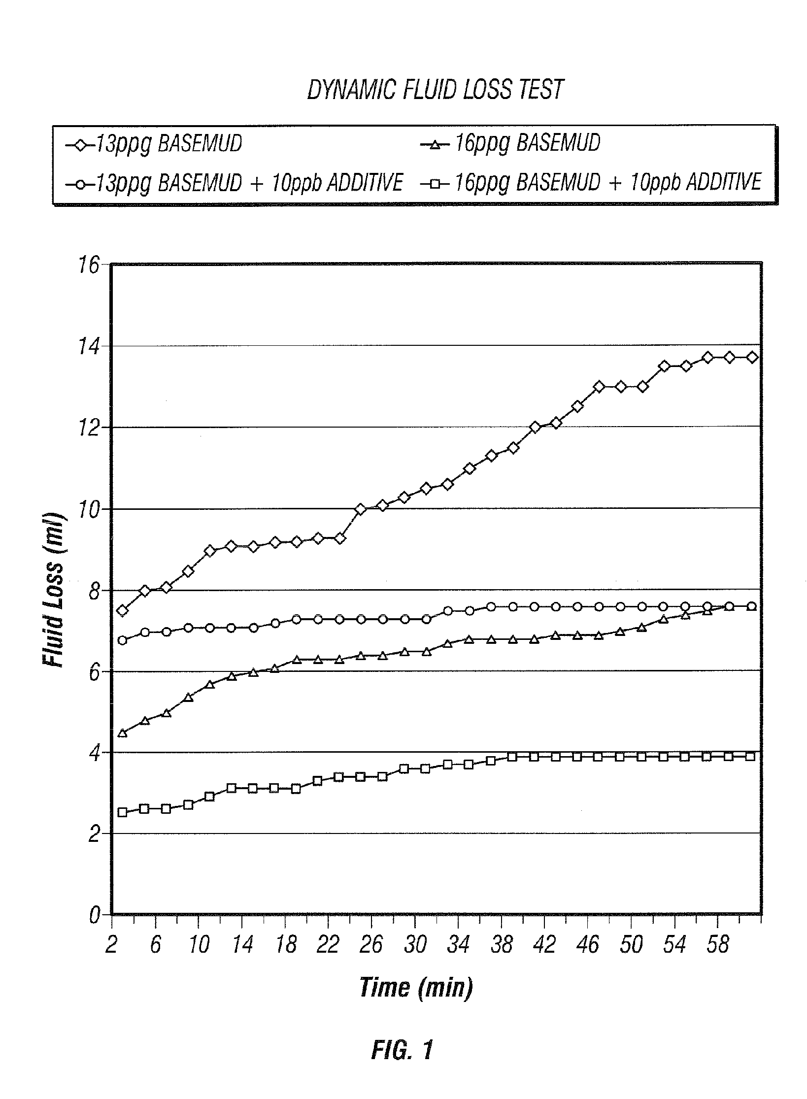
[0033]Simulated tests were conducted on an Ofite Dynamic High Pressure High Temperature apparatus (DHPHT). The apparatus is designed to simulate conditions present within the well. The apparatus is a stainless steel pipe having an inside diameter of 5.7 cm (2.25 in.), a volume of 500 mL, and is capped at each end. The apparatus is equipped with an impeller which causes the mud to flow in a pattern that simulates the use of drilling fluid within the drill pipe (i.e. the fluid flows down the center of the test apparatus and returns along the walls of the test apparatus. On one end of the testing apparatus is a porous disk from which seepage measurements are taken. Measurements are taken at an initial starting point, and then at 2 minute intervals for a total of 60 minutes. The test is designed to demonstrate the ability of a given material to prevent seepage and loss circulation, as well as predicting the ability of the material to form a stable filter cake in the well bore. The tests...

example 2

[0040]Tests were conducted using a 16 ppg mud having a synthetic / water ratio of approximately 73 / 27 and containing approximately 35% solids by volume. The loss control additive, having a composition of 50% by weight PSF, 25% by weight lignite, and 25% by weight fully reacted phenol-formaldehyde resin, was tested at a concentration of 10 pounds per barrel of drilling fluid. Tests were conducted 3.5 MPa (2000 psi) and a temperature of 93° C. (200° F.). Seepage was measured over a 150 micron disk.

[0041]Initial spurt measurements for the test sample were approximately 0 mL and a total fluid loss of approximately 0.8 mL. The base mud had an initial spurt measurement of approximately 24.4 mL and a total fluid loss of approximately 26.4 mL. Thus, fluid loss in the sample having the loss control additive was approximately 40% of that for the base mud.


PUM

PropertyMeasurementUnit
diameteraaaaaaaaaa
diameteraaaaaaaaaa
densityaaaaaaaaaa

Abstract

A method and drilling fluid additive composition are provided for reducing lost circulation and seepage loss when synthetic or oil based drilling fluid is used. The method includes injecting drilling fluid and 1 to 50 pounds per barrel of a loss control additive having a composition comprising 20 to 80 parts by weight fibrous particles, 10 to 40 parts by weight lignite, and 10 to 40 parts by weight phenol-formaldehyde resin.

Description

CROSS REFERENCE TO RELATED APPLICATION[0001]This application claims priority to U.S. Provisional Application Ser. No. 60 / 481,966 filed in the United States Patent and Trademark Office on Jan. 29, 2004.BACKGROUND[0002]A new method and composition designed to eliminate problems associated with seepage loss and lost circulation of synthetic and oil based drilling fluids during drilling operations. More particularly, the method involves injecting a mixture into the well bore and the lost circulation zone, and the mixture forming a barrier within the well bore to prevent further loss of fluids.[0003]Drilling fluids, or drilling muds as they are often known, are generally slurries of clay solids or polymers used in the drilling of wells in the earth for the purpose of recovering hydrocarbons and other fluid materials. Typically, a drilling mud is circulated down through the drill pipe, out the drill bit, and back to the surface through the annulus between the drill pipe and the borehole w...

Claims


Application Information

Patent Timeline
Patent Type & Authority Patents(United States)
IPC IPC(8): C09K8/36E21B43/22
CPCC09K8/502C09K8/32
Inventor VERRET, ROBIN J.
Owner TURBO CHEM INT
Why Eureka
Try Eureka