Photoelectric detector

a detector and photoelectric technology, applied in the field of photoelectric detectors, can solve the problems of affecting the reliability of the output information of the detector, the risk of lenses also increasing the risk of crosstalk, so as to achieve the effect of simple and inexpensive photoelectric detectors, effective and reliable, and easy reproducibility

Active Publication Date: 2007-11-20
SCHNEIDER ELECTRIC IND SAS
View PDF6 Cites 3 Cited by
  • Summary
  • Abstract
  • Description
  • Claims
  • Application Information

AI Technical Summary

Benefits of technology

[0007]According to one aspect of the present invention a simple and inexpensive photoelectric detector is provided that makes possible for the incoming and outgoing light rays of the photoelectric detector to be satisfactorily isolated from each other within a small space. According to another aspect of the present invention it is possible to position the various elements of the detector with respect to one another to be effective and reliable, and easily reproducible on an industrial scale over time, so as to ensure a correct operation of the manufactured detectors.

Problems solved by technology

It is therefore necessary to prevent the phenomenon of crosstalk, i.e., the risk that might arise when the incoming and outgoing light rays become interchanged, which would greatly impair the reliability of the output information from the detector.
Moreover, a photoelectric detector often includes lenses placed in front of the emit and receive members in order to improve their sensitivity and their performance and these lenses also increase the risk of crosstalk.
Likewise, slight positioning discrepancies between the various members of the detector and a dispersion in the tolerance values from one manufacturing batch to another may increase the crosstalk phenomenon.

Method used


Image

  • Photoelectric detector
  • Photoelectric detector
  • Photoelectric detector

Examples


Embodiment Construction

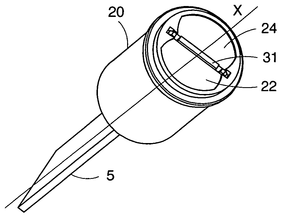
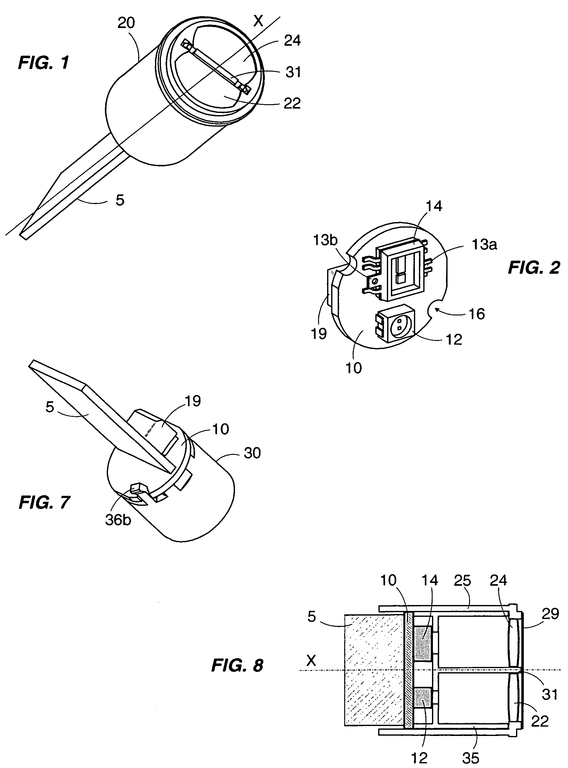
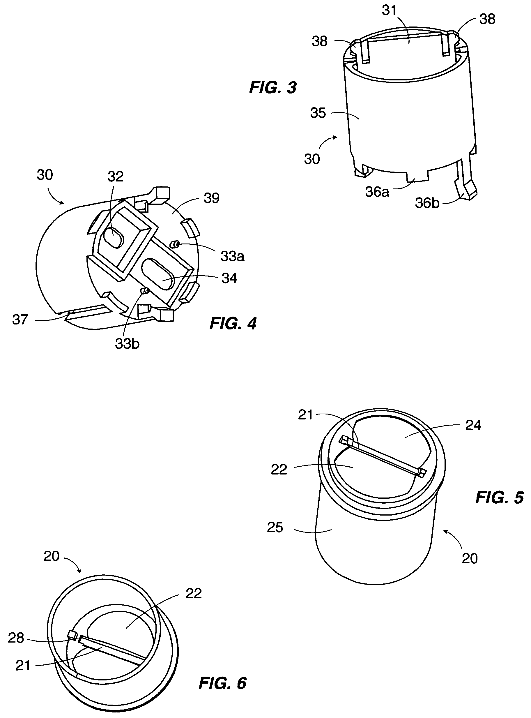
[0018]As shown in FIG. 8, a photoelectric detector, also called a photoelectric cell, includes an emit member 12 capable of emitting at least a first light signal in a direction approximately parallel to the longitudinal axis X of the detector, and a receive member 14 capable of receiving at least a second light signal. The received second light signal originates from the reflection of the emitted first light signal off a reflector or off a target (not shown) to be detected, depending on the use of the detector. The receive member 14 is provided with at least one photoreceptive component that can deliver an electrical signal representative of the second light signal.

[0019]The detector can operate either in a reflex detector mode or in a proximity detector mode. It can also operate in both of these modes. To do so, the emit member 12 may include a photoemissive component capable of emitting a light signal whose wavelength lies within the red spectrum, and a photoemissive component ca...


PUM


Abstract

A photoelectric detector includes an electronic card connected to an emit member and a receive member, the emit member emits at least a first light signal, and the receive member receives at least a second light signal reflected from the first light signal; a cap that includes an emit lens and a receive lens made of a translucent material and positioned in front of the emit member and the receive member, respectively; and a fixing support made of an opaque material to which the card and the cap are fixed. The support has a protruding central blade that is inserted into a separating slot in the cap, between the emit lens and the receive lens.

Description

CROSS-REFERENCE TO RELATED APPLICATIONS[0001]This application claims priority to French Patent Application No. 04 52405, filed Oct. 22, 2004, the entire contents of which are incorporated herein by reference.BACKGROUND OF THE INVENTION[0002]1. Field of the Invention[0003]The present invention relates to a photoelectric detector that includes a member for emitting a light signal and a member for receiving a reflected light signal. The photoelectric detector outputs information indicative of the presence of a target to be detected or a distance to the target to be detected along a path of the light signal.[0004]2. Discussion of the Background[0005]Photoelectric detection devices are well known and can usually be divided into two categories. The first category includes systems that are called thru-beam type systems. The emit member and the receive member of these devices are placed at two points distanced apart and the target is detected when the target crosses a light signal between t...

Claims


Application Information

Patent Timeline
Patent Type & Authority Patents(United States)
IPC IPC(8): H01J5/16
CPCG08B13/184G08B13/183
Inventor CHARRIER, PIERREGAILLEDRAT, JOEL
Owner SCHNEIDER ELECTRIC IND SAS
Why Eureka
Try Eureka