Optical device

a technology of optical devices and optical components, applied in the field of optical devices, can solve the problems of deteriorating the aberration balance between the front group and the rear group, affecting the quality of the image, and affecting the image quality of the front group, etc., and achieves the effects of small focal shift, small compression rate, and low cost and compact structur

Inactive Publication Date: 2007-11-20
ALPS ALPINE CO LTD
View PDF13 Cites 15 Cited by
  • Summary
  • Abstract
  • Description
  • Claims
  • Application Information

AI Technical Summary

Benefits of technology

[0017]Accordingly, the object of the present invention is to provide an optical device which allows a small number of lenses to cover the wide field angle in excess of 180°, and to realize a projection with small compression rate around the viewing surface (isometric projection, three-dimensional projection and the like) by using plastic lens, which can be used as an inexpensive and compact super-wide lens with the small focal shift due to the temperature change.
[0025]The present invention is structured to allow a small number of lenses to cover the wide field angle in excess of 180°, to realize a projection with small compression rate around the viewing surface (isometric projection, three-dimensional projection and the like) by preferentially using the plastic lens, and to be inexpensive and compact having a the small focal shift due to the temperature change.

Problems solved by technology

As all the lenses of the lens system are spherical glass lenses, it is difficult to cover the field angle in excess of 90°, and accordingly, it is difficult to realize the projection with a small compression rate around the viewing surface, for example, isometric projection, three-dimensional projection and the like.
If the field angle is intended to be further widened while using the plastic lens, it may increase the focal shift due to the temperature change as well as deteriorate the aberration balance between the front group and the rear group.
Contrary to Japanese Unexamined Patent Application Publication No. 2005-221920, as the power of the front group of the super-wide lens is relatively lower, it is not suitable for the wider field angle.

Method used


Image

  • Optical device
  • Optical device
  • Optical device

Examples


embodiments

[0063]Embodiments of the present invention will be described. In the embodiments as described below, the optical surface of at least one lens is made aspherical. The formula for the aspherical surface is expressed in the formula 1. However, the present invention is not limited to the aspherical surface as expressed by the formula 1.

[0064]z=ch21+1-(1+k)⁢c2⁢h2+A4⁢h4+A6⁢h6+A8⁢h8+…+A26⁢h26formula⁢⁢1

where z denotes a surface depth along the optical axis from the reference plane in contact with the top end of the aspherical surface, c denotes an inverse of the curvature radius R of the optical surface, h denotes the height of the plane from the optical axis, k denotes a cone constant indicating the quadratic surface, and A4 to A26 denotes the aspherical surface correction coefficient.

[0065]Referring to Table 7, in all the embodiments, the horizontal interfacial angle is set to 190° (half field angle is set to 95°).

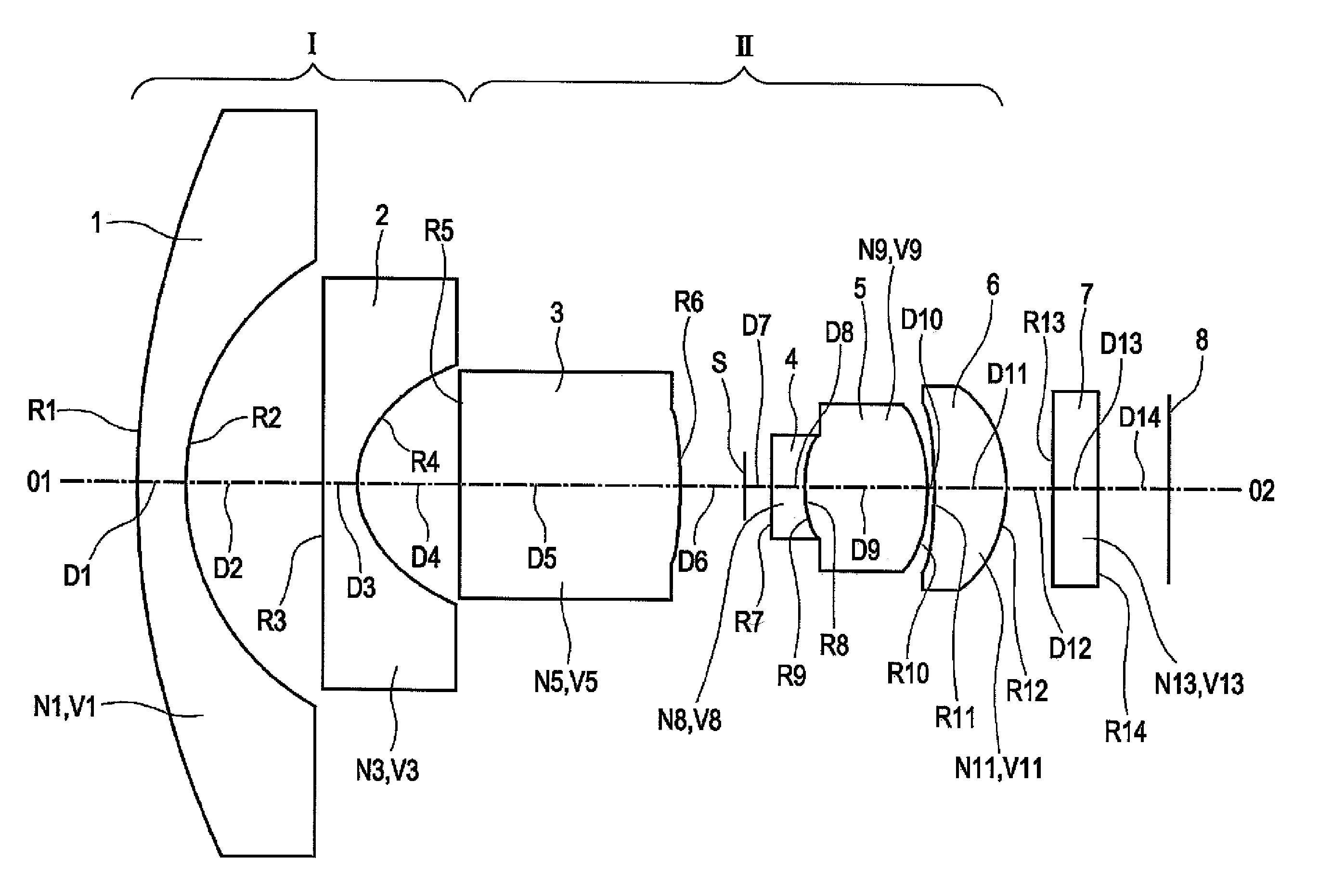
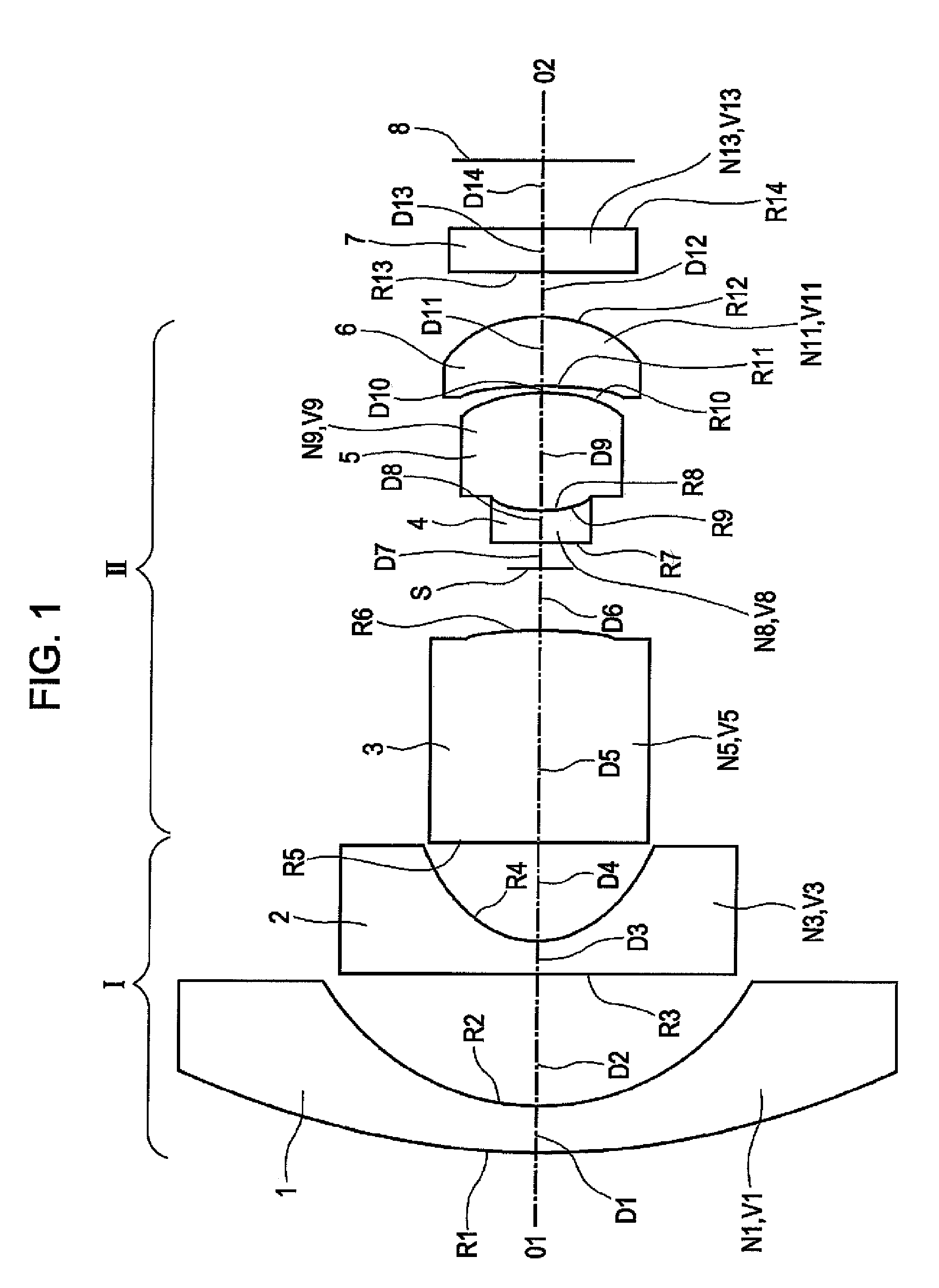
[0066]The respective codes shown in FIGS. 1 and 3, and in Tables 1 to 7 are...


PUM


Abstract

A front group is formed of a negative first lens as a meniscus lens which is convex at the object side and a negative second lens, and a rear group is formed of a biconvex positive third lens, an aperture stop, a negative fourth lens and a biconvex positive fifth lens. The first lens is a glass lens, and the second lens is a plastic aspherical lens. The following conditions are satisfied: −2.4<fI / f<−1.55, 0.15<f2 / f1<0.35, va<29, and vb>50, where f denotes a focal distance of a whole system, f1 denotes a focal distance of the first lens, f2 denotes a focal distance of the second lens, fI denotes a focal distance of the front group, va denotes an average value of abbe numbers of the third and the forth lenses, and vb denotes an average value of abbe numbers of the rest of the lenses.

Description

[0001]This application claims the benefit of priority under 35 U.S.C. § 119 to Japanese Patent Application No. 2006-056312, filed Mar. 2, 2006, which is hereby incorporated by reference in its entirety.BACKGROUND OF THE INVENTION[0002]1. Field of the Invention[0003]This invention relates to an optical device used as a super-wide image pickup lens that forms an image of a subject on a light receiving surface.[0004]2. Description of the Related Art[0005]A wide-angle lens that covers a wide field has been generally employed in on-board cameras and / or monitoring cameras. Accompanied with the advanced image processing technology, the super-wide lens capable of covering the wider field by correcting distortion of the image in real time has been increasingly demanded. Optical devices that satisfy requirements, such as compact size, high resolution, and low cost are very desirable, especially in view of the demands relating to the space for accommodating such devices and the required higher...

Claims


Application Information

Patent Timeline
Patent Type & Authority Patents(United States)
IPC IPC(8): G02B13/18G02B9/04
CPCG02B13/04G02B13/18G02B13/06
Inventor YAMASHITA, TATSUMAROMATSUO, EIKI
Owner ALPS ALPINE CO LTD
Why Eureka
Try Eureka