Apparatus and method for GFP frame transfer
a frame transfer and apparatus technology, applied in the field of gfp (generic frame procedure) frame transfer apparatus and gfp frame transfer method, can solve the problems of inability to perform performance monitoring of the above-described inability to perform monitoring of the end-to-end path from the sonet node, and inability to realize the performance monitoring of the end-to-end path using the fcs field
- Summary
- Abstract
- Description
- Claims
- Application Information
AI Technical Summary
Benefits of technology
Problems solved by technology
Method used
Image
Examples
first embodiment
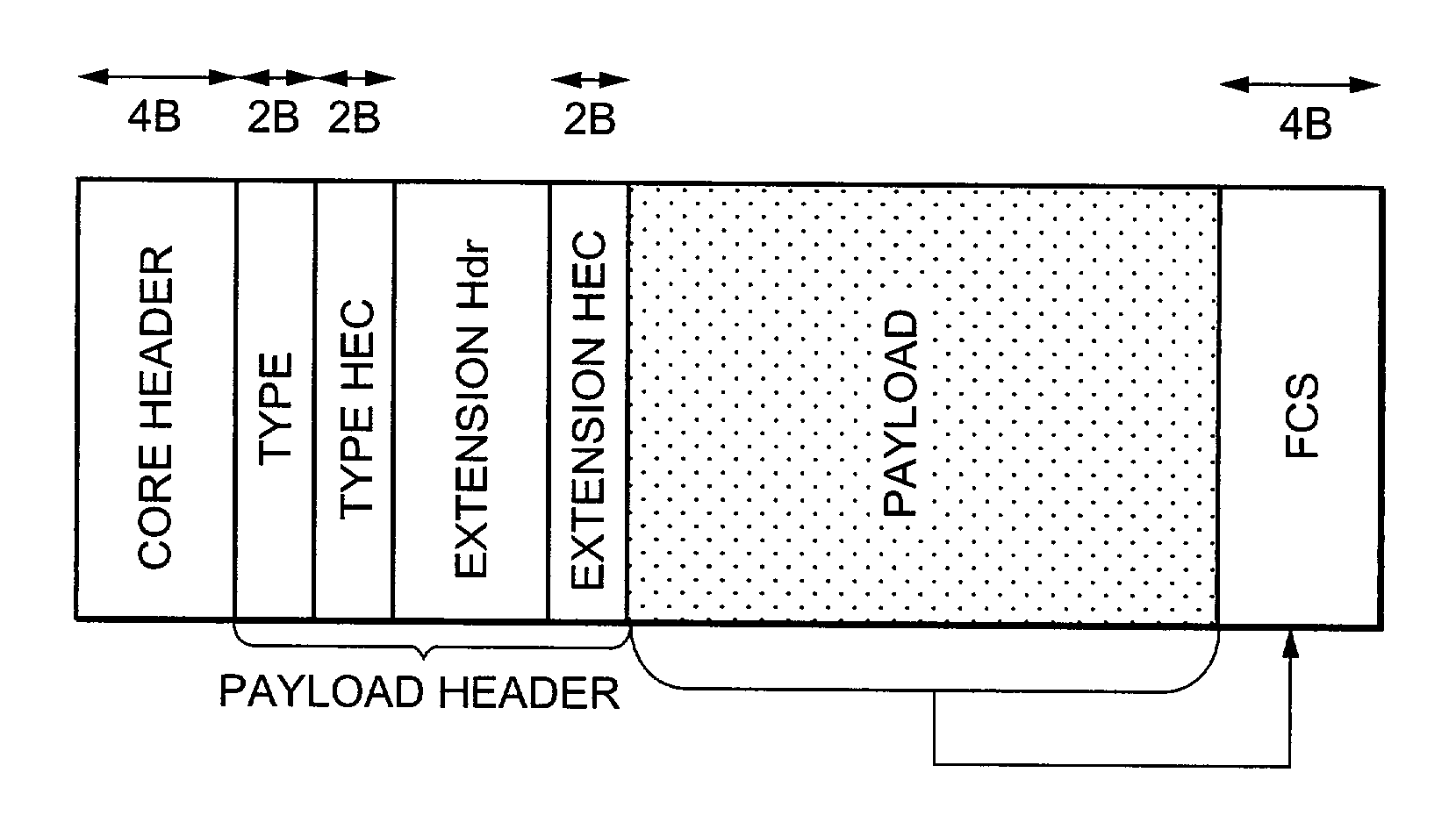
[0051]FIG. 9 is a block diagram showing an example of a network (called a “GFP network”) made up of GFP frame transfer apparatuses according to a first embodiment of the present invention. This embodiment will be explained by taking a ring connection GFP network formed as a SONET ring as an example. For this effect, suppose a GFP ring frame having the payload header configuration shown in FIG. 7 is used as the GFP frame to be transferred within this GFP network.
[0052]According to FIG. 9, the ring-shaped GFP network in this embodiment is constructed of a plurality of GFP nodes 1 (N1, N2, . . . N7) connected in a ring shape. Each GFP node 1 is connected to 1 or a plurality of subscriber networks. For simplicity, suppose each GFP node 1 is connected to and accommodates one subscriber network in the following explanations. Each GFP node 1 has a plurality of ports and each port is provided with a port number. Suppose, for example, the west side port is assigned port number “1”, the east ...
second embodiment
[0101]Then, a second embodiment of the present invention will be explained.
[0102]This second embodiment uses the conventional FCS generation target area without changing it as the FCS generation target area and adopts a different calculation method as the FCS recalculation method. It carries out FCS generation (calculation) at the GFP node 1 of Ingress and an FCS check at the intermediate GFP node 1 and GFP node 1 of Egress according to the conventional specification. On the other hand, when an FCS is recalculated at the intermediate GFP node 1, this embodiment uses the changed difference of the payload header and original FCS to calculate a new FCS.
[0103]The second embodiment calculates a difference between the original (when the GFP node 1 is input) payload header and new (when the GFP node 1 is output) payload header and performs a division by a generating function G(x) of CRC32 calculation with respect to this difference. The exclusive OR between the remainder in the division re...
third embodiment
[0158]Next, a third embodiment of the present invention will be explained.
[0159]As shown in FIG. 20, as the FCS generation target area, this third embodiment uses the conventional FCS generation target area without any modification thereto and defines a new error notification bit in the payload header. This error notification bit can be defined, for example, in part of the Spare field of the payload header in the case of the GFP ring frame.
[0160]FIG. 21 is a schematic view showing performance monitoring of an end-to-end path using the FCS field and error notification bit in the third embodiment of the present invention. FIG. 21 is an example of transfer of a GFP frame in part (N2→N5) of the ring-shaped GFP network in FIG. 9 as in the case of FIG. 15.
[0161]As shown in FIG. 21, when an error occurs in a GFP link and the error is detected by an FCS check at the GFP node 1 that has received this GFP frame, the GFP frame interface section 13 of the GFP frame termination section 5 of the ...
PUM
 Abstract
Description
Claims
Application Information
 - R&D
- Intellectual Property
- Life Sciences
- Materials
- Tech Scout
- Unparalleled Data Quality
- Higher Quality Content
- 60% Fewer Hallucinations
Browse by: Latest US Patents, China's latest patents, Technical Efficacy Thesaurus, Application Domain, Technology Topic, Popular Technical Reports.
© 2025 PatSnap. All rights reserved.Legal|Privacy policy|Modern Slavery Act Transparency Statement|Sitemap|About US| Contact US: help@patsnap.com


