
Connection module for the connection of a sensor to a fieldbus

a technology for connecting modules and sensors, applied in the field of connection modules for the connection of sensors, can solve the problems of undesirably large amount of actual sensor modules, insufficient known connection modules, and inability to use sensors for other fieldbus types, so as to achieve the effect of substantially reducing device effort and simplifying the control of the switch input/output of the sensor

Active Publication Date: 2007-11-20
SICK AG
View PDF13 Cites 15 Cited by
  • Summary
  • Abstract
  • Description
  • Claims
  • Application Information

AI Technical Summary

Benefits of technology

"The invention is a connection module for a sensor network that makes it easier to connect and replace sensors and modules. The module has a parallel interface with a serial data interface and a separate switch interface, and an integrated I / O circuit that converts switching data between the two interfaces. The I / O circuit also provides a gateway circuit for connecting the sensor to the fieldbus. The module simplifies the control of the sensor's switch inputs and allows for easy replacement of the sensor or the connected module. The module reduces the device effort and simplifies the process mapping of the control. The permanent memory in the module allows for easy storage and retrieval of operating parameters, and the operating parameters can be transmitted to the gateway circuit and I / O circuit from a connected sensor."

Problems solved by technology

A fieldbus interface integrated in the sensor, however, makes the actual sensor module undesirably expensive and undesirably voluminous for some applications.
The relevant sensor is moreover admittedly adapted to a specific fieldbus; but the sensor can no longer easily be used for other fieldbus types.
Known connection modules have proven to be insufficient, in particular with optoelectronic sensors, since these have digital switch inputs and outputs in addition to a serial data interface and since additional circuits are therefore required to bring about the desired adaptation to a specific fieldbus.
With the known connection modules, the parameterization, i.e. the adaptation of the gateway circuit to the fieldbus addressing and the fieldbus protocol is moreover undesirably complex since two devices (sensor and gateway circuit) have to be addressed.

Method used


Image

  • Connection module for the connection of a sensor to a fieldbus
  • Connection module for the connection of a sensor to a fieldbus

Examples


Embodiment Construction

[0034]The following description of the preferred embodiments is merely exemplary in nature and is in no way intended to limit the invention, its application, or uses.

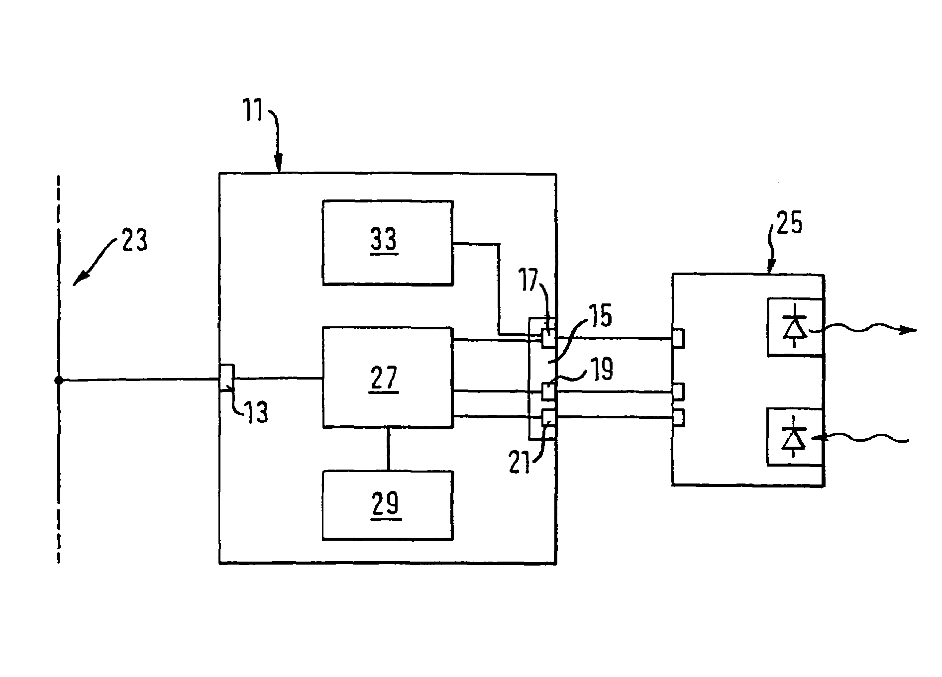
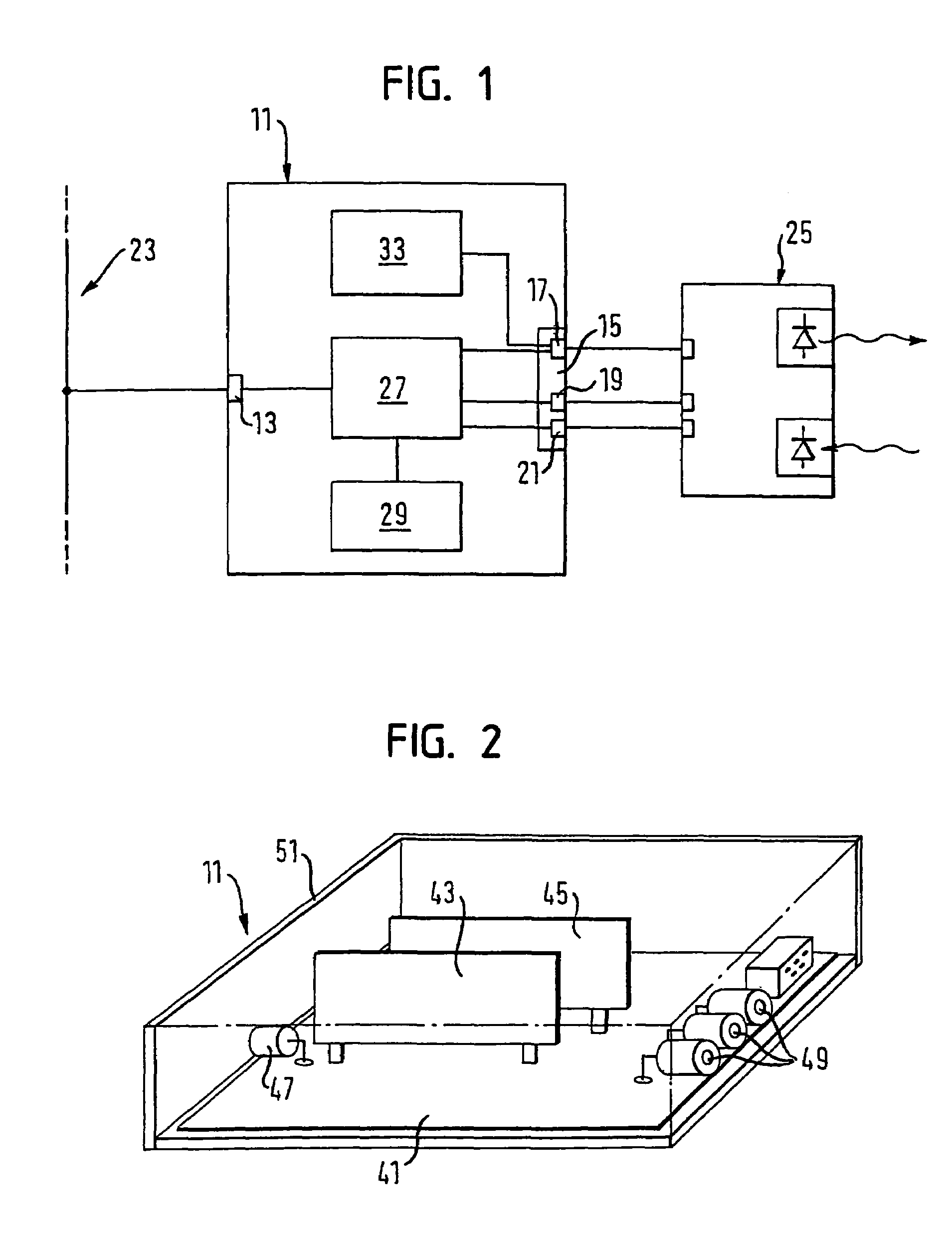
[0035]FIG. 1 shows, in a block diagram, a connection module 11 with a serial bus interface 13 and a parallel sensor interface 15. The latter has a serial data interface 17 and—parallel thereto—a switch input 19 and a switch output 21. The connection module 11 is connected to a fieldbus 23, for example of the type Profibus or DeviceNet, via the bus interface 13. Furthermore, the connection module 11 is connected via the serial data interface 17 and via the switch input 19 and the switch output 21 of the sensor interface 15 to an optoelectronic sensor 25, for example to an optical code reader.

[0036]The connection module 11 furthermore has a gateway circuit 27 which is connected to the bus interface 13 and to the serial data interface 17 of the sensor interface 15. The gateway circuit 27 serves for the conversion of the da...


PUM


Abstract

The invention relates to a connection module for the connection of a sensor, in particular of an optoelectronic sensor, to a fieldbus, comprising a sensor interface for the connection of the connection module to an interface of a sensor, a serial bus interface for the connection of the connection module to an interface of a fieldbus and a gateway circuit which is connected to the bus interface and to the sensor interface in order to convert data received at the bus interface into a data format of a connected sensor and vice versa. The sensor interface of the connection module is made as a parallel interface. At least one I / O circuit is integrated into the connection module and is connected to the bus interface and to the sensor interface. The invention further relates to a method for the connection of a sensor to a fieldbus via a connection module.

Description

FIELD OF THE INVENTION[0001]The invention relates to a connection module for the connection of a sensor, in particular of an optoelectronic sensor, to a fieldbus, comprising a sensor interface for the connection of the connection module to an interface of a sensor, a serial bus interface for the connection of the connection module to an interface of a fieldbus and a gateway circuit which is connected to the bus interface and to the sensor interface in order to convert data received at the bus interface into a data format of a connected sensor and to output them at the sensor interface and to convert data received at the sensor interface into a data format of the fieldbus and to output them at the bus interface.BACKGROUND OF THE INVENTION[0002]The background of the invention is the networking of sensors, for example of one-dimensional or two-dimensional optical code readers or of laser measuring systems, via a digital fieldbus, for example of the type Profibus or DeviceNet. It is kno...

Claims


Application Information

Patent Timeline
Patent Type & Authority Patents(United States)
IPC IPC(8): G06F13/12G05B19/042G08C15/00
CPCG05B19/0423G05B2219/25006
Inventor ASCHENBRENNER, JOHANNES
Owner SICK AG
Learn More