Camera-lens position regulating method and apparatus, and camera thereof

A technology for adjusting a device and a camera, which is applied to the camera, the camera body, installation and other directions, and can solve the problems of reduced failure-free time of the device, complicated structure, and increased weight of the camera.

Inactive Publication Date: 2011-09-07
RICOH KK
View PDF2 Cites 0 Cited by
  • Summary
  • Abstract
  • Description
  • Claims
  • Application Information

AI Technical Summary

Problems solved by technology

[0006] The inventor also believes that setting several motors and other power devices in a single camera will increase the cost, increase the weight of the camera, complicate the structure, and reduce the mean time between failures of the device.
[0007] In the case of using one motor to drive in two directions, although it can reduce the weight and structural complexity, it can be regarded as a logic circuit to control the mechanical energy of a single motor, which is expensive

Method used


Image

  • Camera-lens position regulating method and apparatus, and camera thereof
  • Camera-lens position regulating method and apparatus, and camera thereof
  • Camera-lens position regulating method and apparatus, and camera thereof

Examples


Embodiment Construction

[0161] Embodiments of the present invention will be described in detail below with reference to the accompanying drawings.

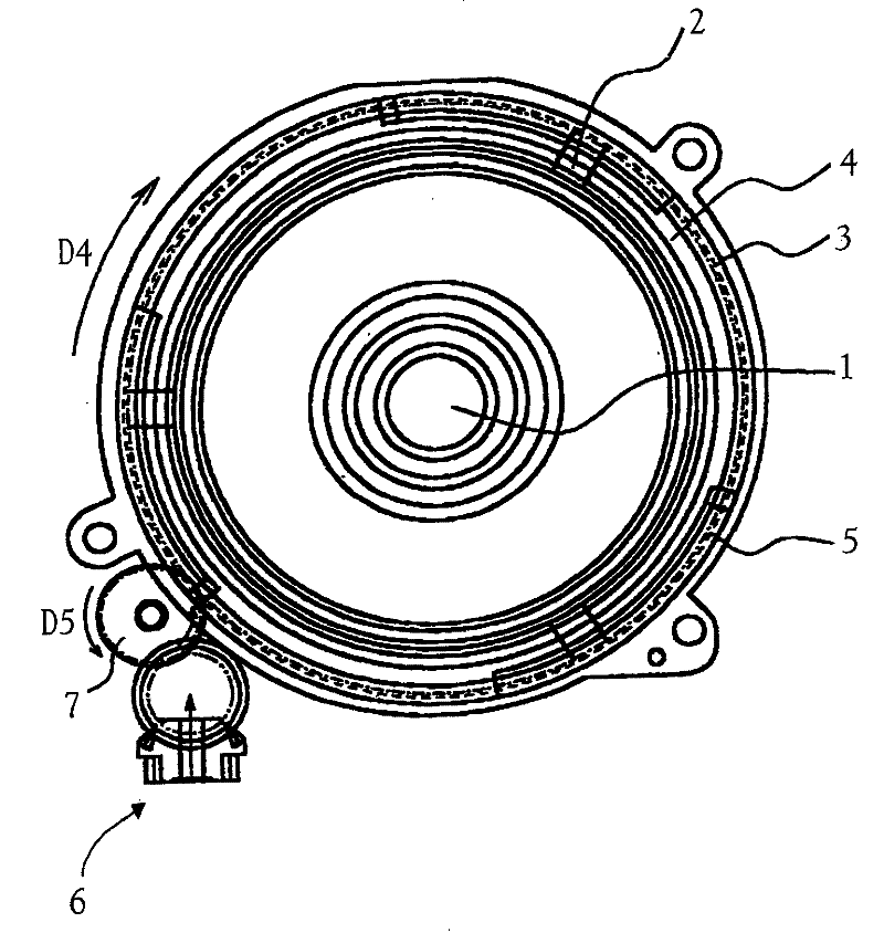
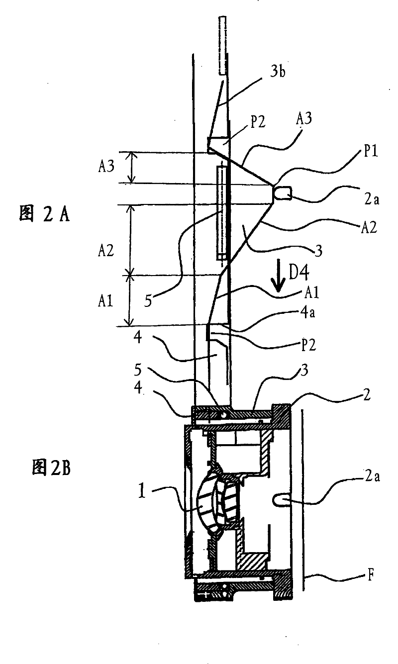
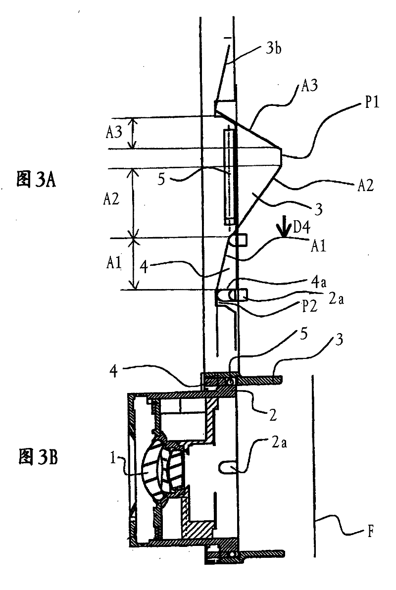
[0162] figure 1 - FIG. 3 shows the configuration of main parts of an auto-focus camera (hereinafter referred to as "auto-focus camera") according to an embodiment of the present invention. in, figure 1 It is a front view of the surrounding composition of the main optical system related to the photographic lens system and its drive unit of the camera according to the embodiment of the present invention; Figure 2A is meant as figure 1 A schematic development diagram of the positional relationship of the cam part, the cam return part, and the lens linkage part of the main components of the camera, Figure 2B From figure 1 The cross-sectional view seen from the side of the structure; Figure 3 shows a different action state from Figure 2, Figure 3A is meant as figure 1 A schematic development diagram of the positional relationship of the cam part, the c...


PUM


Abstract

The invention relates to a camera-lens position regulating method and apparatus, and camera thereof. The camera comprises: a lens holding member, a motor providing revolution driving force in a predetThe invention relates to a camera-lens position regulating method and apparatus, and camera thereof. The camera comprises: a lens holding member, a motor providing revolution driving force in a predetermined direction, a geared ring, a cam, a potential applying element of which one end is connected with one of the geared ring and the cam and the other end is connected with a movable object, and aermined direction, a geared ring, a cam, a potential applying element of which one end is connected with one of the geared ring and the cam and the other end is connected with a movable object, and aclutch for controlling joint and separation between the geared ring and the cam. According to the invention, using mono-directional driving force of the motor to control bi-directional movement of theclutch for controlling joint and separation between the geared ring and the cam. According to the invention, using mono-directional driving force of the motor to control bi-directional movement of thedriving device can realize at least one of focusing operation, film feeding operation, zooming operation, lens retracting operation and shuttering operation, with a cheap structure and without expens driving device can realize at least one of focusing operation, film feeding operation, zooming operation, lens retracting operation and shuttering operation, with a cheap structure and without expensive driving source.ive driving source.

Description

[0001] This application is a divisional application based on the patent application whose filing date is May 5, 1999, application number is 99106325.2, and the title of the invention is "lens position adjustment method and device and camera". technical field [0002] The present invention relates to a lens position adjustment method, a lens position adjustment device, and a camera. More specifically, it relates to a camera that is provided with a drive mechanism and a lens position control mechanism that use only one motor to realize several actions. Driving force, the above-mentioned lens position control mechanism can carry out two-way control to the lens position or other movable devices. Background technique [0003] Generally, in a camera, a driving force of a driving source such as a motor is transmitted to camera components to perform various actions. For example, in a single-focus camera, the actions (1) film feeding, (2) focusing, and (3) shutter release are perform...

Claims


Application Information

Patent Timeline
Patent Type & Authority Patents(China)
IPC IPC(8): G02B7/08G02B7/10G03B9/08G03B17/28H04N5/225
CPCG02B7/102
Inventor 工藤智幸
Owner RICOH KK
Why Eureka
Try Eureka