Injection mold insert block alignment system

a technology of insert blocks and alignment systems, which is applied in the field of injection molding and injection mold tooling, can solve the problems of affecting accuracy, reducing the quality of components that can be molded by the tool, and unable to compensate for wear or other factors, and achieves the effect of easy engagemen

Inactive Publication Date: 2007-11-27
NOKIA CORP
View PDF21 Cites 10 Cited by
  • Summary
  • Abstract
  • Description
  • Claims
  • Application Information

AI Technical Summary

Benefits of technology

[0008]In a further aspect of the invention, the alignment bar has a rectangular cross section with spaced apart oppositely disposed sides and spaced apart oppositely disposed ends. The alignment bar sides may further have chamfered side edges and the alignment bar ends may further have chamfered end edges to allow easy engagement with the alignment channels on the insert blocks.

Problems solved by technology

If the core and cavity insert blocks of a mold tool do not align precisely throughout the mold tool's life, excessive wear of mating shut out faces occurs which in turn causes a degradation in the quality of components that can be molded by that tool.
The positioning of the insert blocks in this manner is a difficult and time consuming process and provides no compensation adjustment for wear or other factors affecting accuracy.
The positioning of the insert blocks in this manner is also difficult and time consuming in the initial set-up and also during subsequent adjustment to compensate for wear or other factors affecting accuracy.
Although this conical self-alignment feature is known in some sectors of the molding industry as stated above, for example, packaging containers and PET bottle preform molds, a similar solution is not satisfactory and suitable for use with technical molds such as the molds used to produce products and parts in the telecom sectors.

Method used


Image

  • Injection mold insert block alignment system
  • Injection mold insert block alignment system
  • Injection mold insert block alignment system

Examples


Embodiment Construction

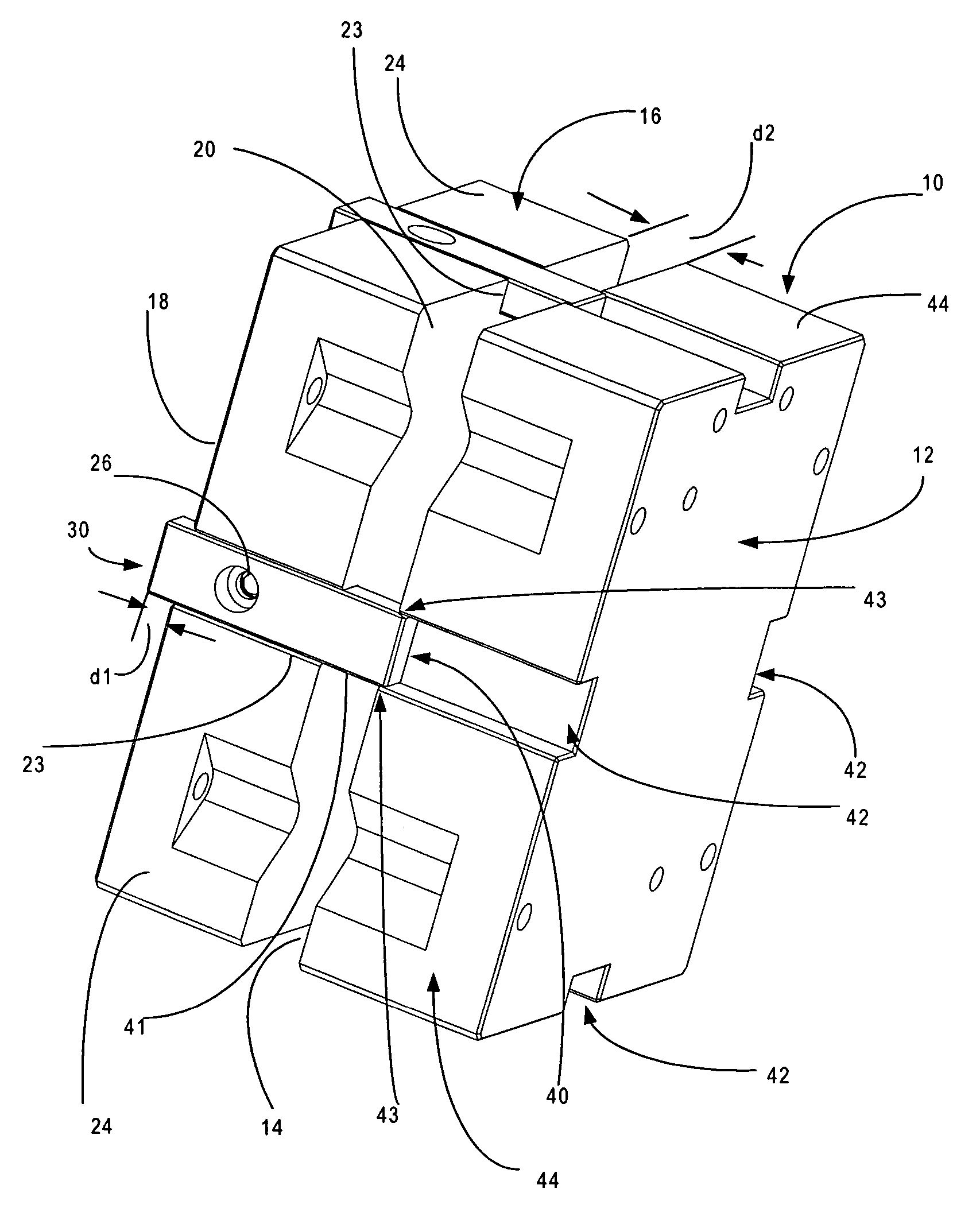
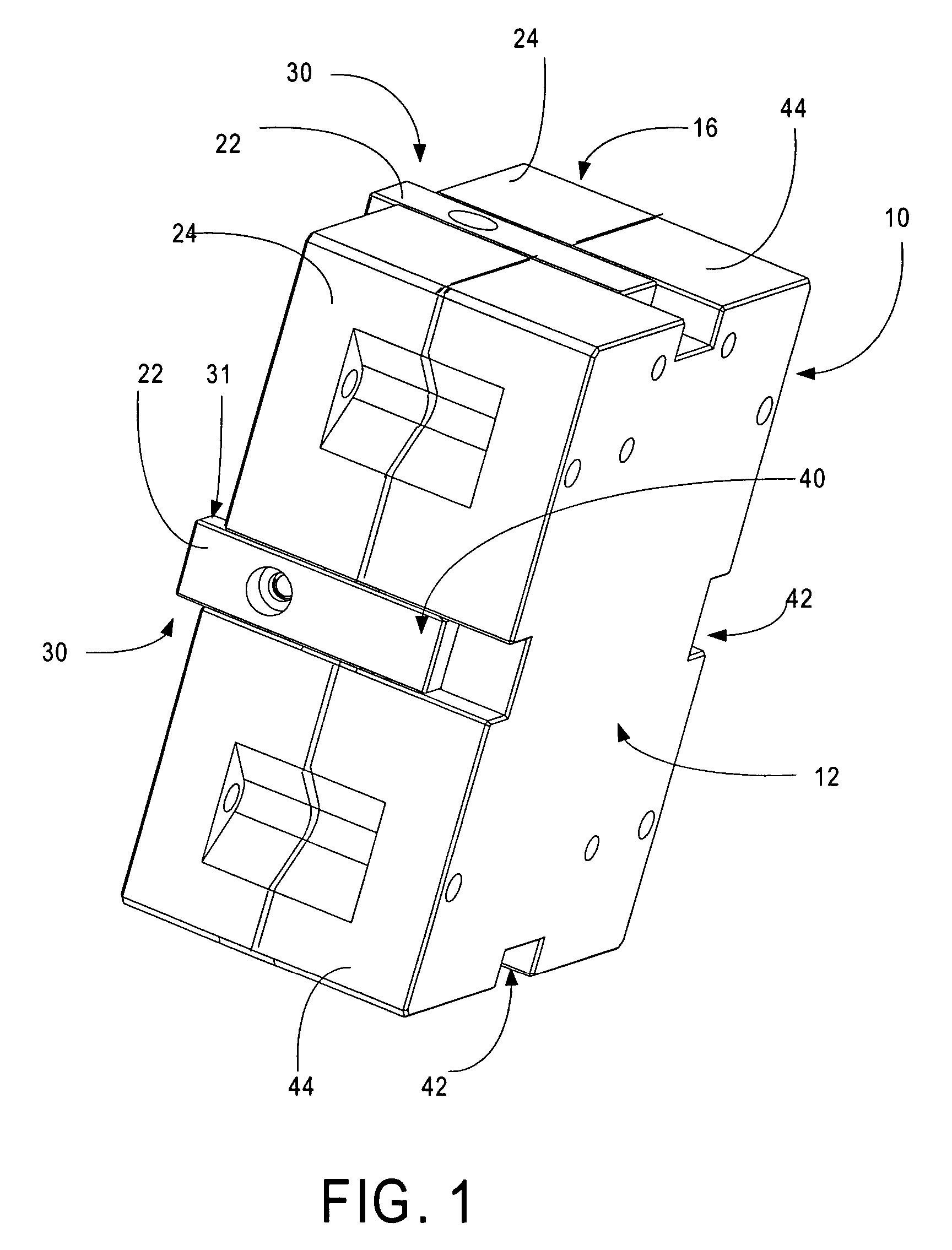
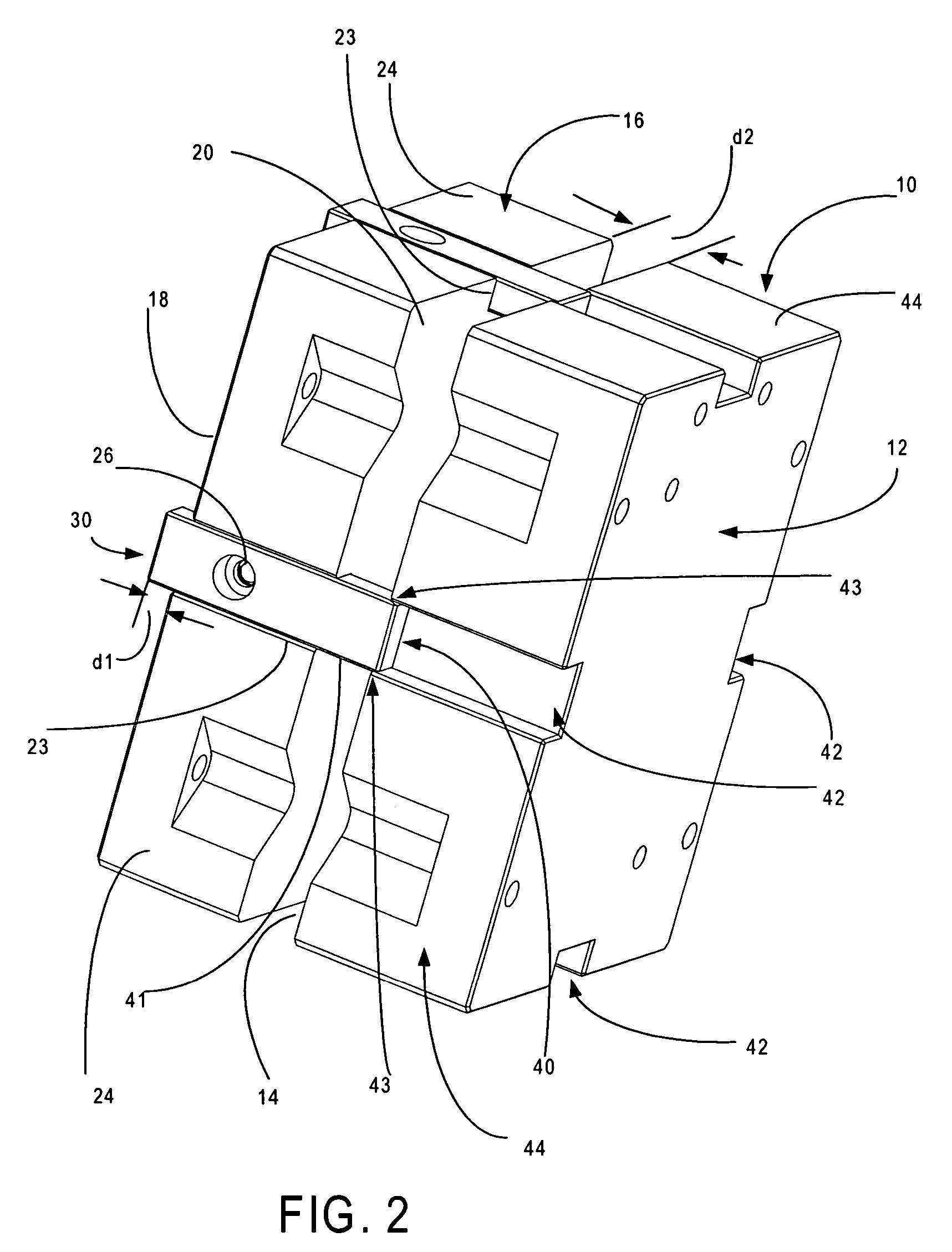
[0018]Turning now to the drawings and considering the invention in further detail, an alignment system embodying the present invention for self alignment of core and cavity insert blocks in an injection mold tool is disclosed in an exemplary embodiment. The alignment system is incorporated within the injection mold cavity and allows the adjustment and alignment of each core insert block and cavity insert block set or pair during the assembly of the injection mold tool thereby eliminating the need to rely on the mold base accuracy for alignment and position of the insert blocks. For purposes of explanation of the invention and to gain a better understanding, the invention is described by way of the following illustrative example. A core insert block generally designated 10 has a mold base facing side major surface 12 and an oppositely disposed molding face surface generally designated 14. A cavity insert block generally designated 16 includes a mold base facing major surface generall...


PUM

PropertyMeasurementUnit
distanceaaaaaaaaaa
alignment forceaaaaaaaaaa
lengthaaaaaaaaaa

Abstract

Alignment bars are mounted to a core or cavity insert block and a portion of one end of the alignment bar projects above the plane of a molding face surface and engages with a corresponding respective mating alignment channel in the other of the core or cavity insert block when the blocks are moved into a closed operative position. A portion of the other end of the alignment bar projects below the plane of a mold base plate facing surface defining keys for insertion into pockets formed in the mold base plate of a mold base for precise fixed positioning of the insert block on the mold base plate. The other insert block is carried by a co-operating mold base and the position of the insert block is moved into alignment with the insert block mounted on the other mold base.

Description

TECHNICAL FIELD[0001]The present invention relates generally to injection molding and injection mold tooling and deals more particularly with an alignment system for insert blocks used in injection mold tools.BACKGROUND OF THE INVENTION[0002]In the prior art, conventional mold tools require very accurate tolerances to be achieved between the alignment of the sides of core and cavity insert blocks. To achieve the precise alignment, very accurate tolerances must be held on a long tolerance loop which involves not only the core and cavity insert blocks, but also elements of the mold base that are supporting the insert blocks. If the core and cavity insert blocks of a mold tool do not align precisely throughout the mold tool's life, excessive wear of mating shut out faces occurs which in turn causes a degradation in the quality of components that can be molded by that tool.[0003]Usually, in technical mold tools in the prior art, the core insert block and cavity insert block are either r...

Claims


Application Information

Patent Timeline
Patent Type & Authority Patents(United States)
IPC IPC(8): B29C33/30
CPCB29C45/2606B29C45/2673
Inventor PARMENTER, PHILIPDREES, GUIDOSCHAD, ROBERT DIETRICH
Owner NOKIA CORP
Why Eureka
Try Eureka